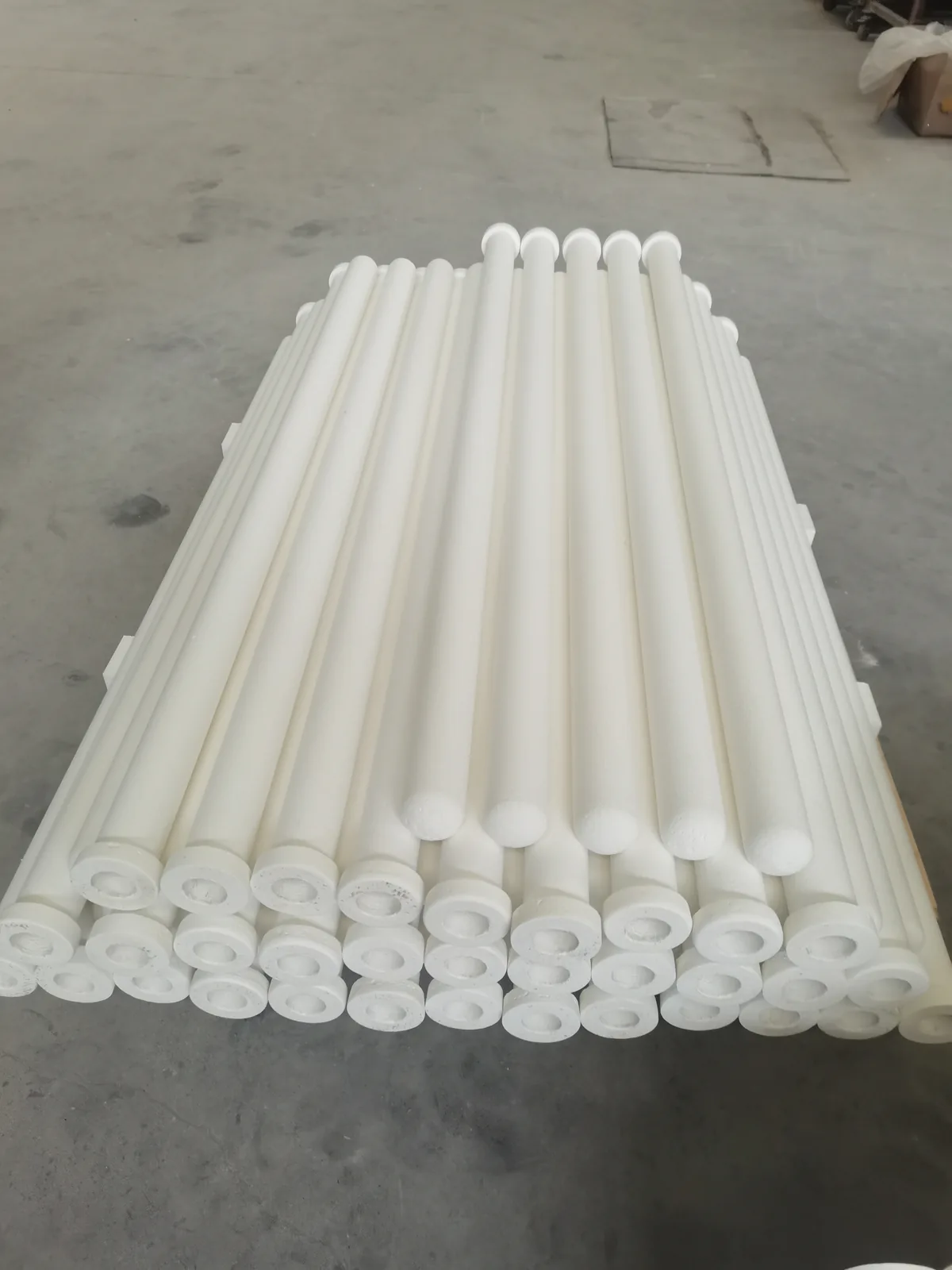
Hot Gas Filtration with Ceramic Fiber Filter Tubes

Anchor-Tech supplies rigid ceramic fiber filter tubes and complete hot gas filtration units that clean industrial exhaust at temperatures where bag filters and ESPs reach their limits. One vessel removes dust, acid gases, NOx and dioxins: particulate emissions stay below 5 mg/Nm³, DeNOx efficiency exceeds 95% inside the SCR window, and filter grades cover continuous service at 600 °C and 1,000 °C.
Why Conventional Filters Struggle with Hot Gas
Plants running glass furnaces, incinerators, kilns and smelters face the same constraint: the gas that needs cleaning is hot, often corrosive, and carries fine PM2.5 and sub-micron particles. Cooling the gas first wastes recoverable heat and adds equipment. The three mainstream options compare as follows:
| Technology | Strengths | Limits in hot gas service |
|---|---|---|
| Electrostatic precipitator (ESP) | Good collection efficiency; no secondary pollution | High energy consumption; performance swings with fuel and fly ash; large footprint; cannot hold ultra-low emission levels |
| Bag filter (fabric baghouse) | Good filtration; works with alkaline sorbent injection against acid gases | Not heat-resistant; hardens and ruptures in acid gas; short service life; mediocre PM2.5 capture; unstable ultra-low emission |
| Ceramic fiber filter (CF) | Very high filtration capacity; resistant to high temperature, acid and alkali; saves water and energy; long service life; no secondary pollution; stable ultra-low emission | — |
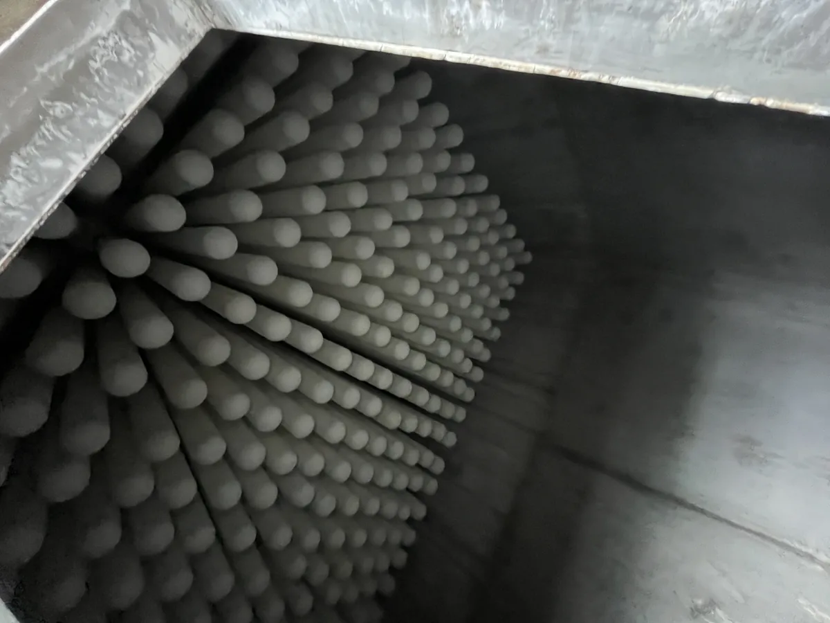
Ceramic filter tubes are rigid, self-supporting candles mounted on the tubesheet of a pulse-jet collector, exactly where filter bags would sit — which makes them a direct retrofit path for existing baghouses. → How to Retrofit a Baghouse to Ceramic Candle Filters
One Unit, Four Duties: Dust, Acid Gas, NOx, Dioxins
A CF hot gas filtration unit is more than a dust collector. With dry sorbent injection and catalyst-loaded filter tubes, a single vessel handles four pollutant groups:
- Dust — captured on the rigid tube surface and pulse-cleaned; outlet stays below 5 mg/Nm³, meeting ultra-low emission requirements.
- Acid gases (SO₂, SO₃, HCl, HF) — neutralized by injected NaHCO₃ or Ca(OH)₂ dry sorbent upstream of the tubes; a dry process that uses no water and creates no wastewater.
- NOx — removed SCR-style by catalyst loaded inside the tube wall, with ammonia or urea injection. The dust cake stays on the tube surface, so the catalyst is shielded from dust blinding and heavy-metal poisoning.
- Dioxins and organic HAPs — decomposed inside the tube wall by selective catalytic oxidation (SCO) into CO₂, H₂O and HCl; no activated carbon bed and no other chemical dosing is required for dioxin destruction.
Optimal combined operating window for dust + acid gas + NOx duty: 250–350 °C.
| Pollutant | Working window | Documented performance |
|---|---|---|
| PM2.5 / PM10 / sub-micron dust | up to ~1,050 °C (grade-dependent) | Outlet <5 mg/Nm³; running ΔP typically <1,500 Pa, long-term <2,500 Pa |
| NOx (SCR, NH₃/urea) | 280–400 °C | >95% DeNOx at 280 °C and above; catalyst service life 7–9 years, 5 years guaranteed |
| SO₂ / SO₃ / HCl / HF (dry sorbent) | Na-based sorbent 320–400 °C; Ca-based 300–450 °C | Na-based sorbent: 85–95% removal (depends on sorbent dose, gas humidity, process design, operating conditions) |
| Dioxins / O-HAPs (SCO) | 170–300 °C, optimum 220–260 °C; inlet SO₂ <50 mg/Nm³ | Dioxin destruction up to 99.5% TEQ; integrated trains achieve dust ≤5, SO₂ ≤30, NOx ≤50 mg/Nm³ (S.T.P., dry) |
| Mercury (Hg) | Brominated powdered activated carbon 260–430 °C | >90% removal (activated carbon at 200 °C: 70–80%) |
| VOC | 230–260 °C | 95% removal |
| CO | 200–300 °C | Removed together with NOx duty |
Ceramic Filter Tube Specifications (White Tube, Non-Catalyst)

The workhorse element is a vacuum-formed ceramic fiber tube with a graded pore structure — pore size graduates from the outer surface inward, so dust forms a surface cake while the wall depth stays open.
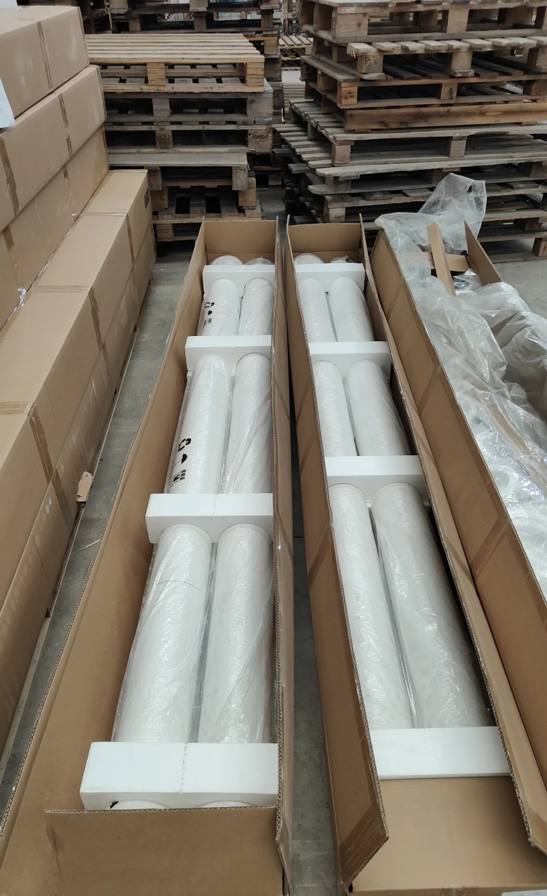
Elements ship in foam-supported cartons, stackable up to 10 high, and should be unpacked only immediately before installation.
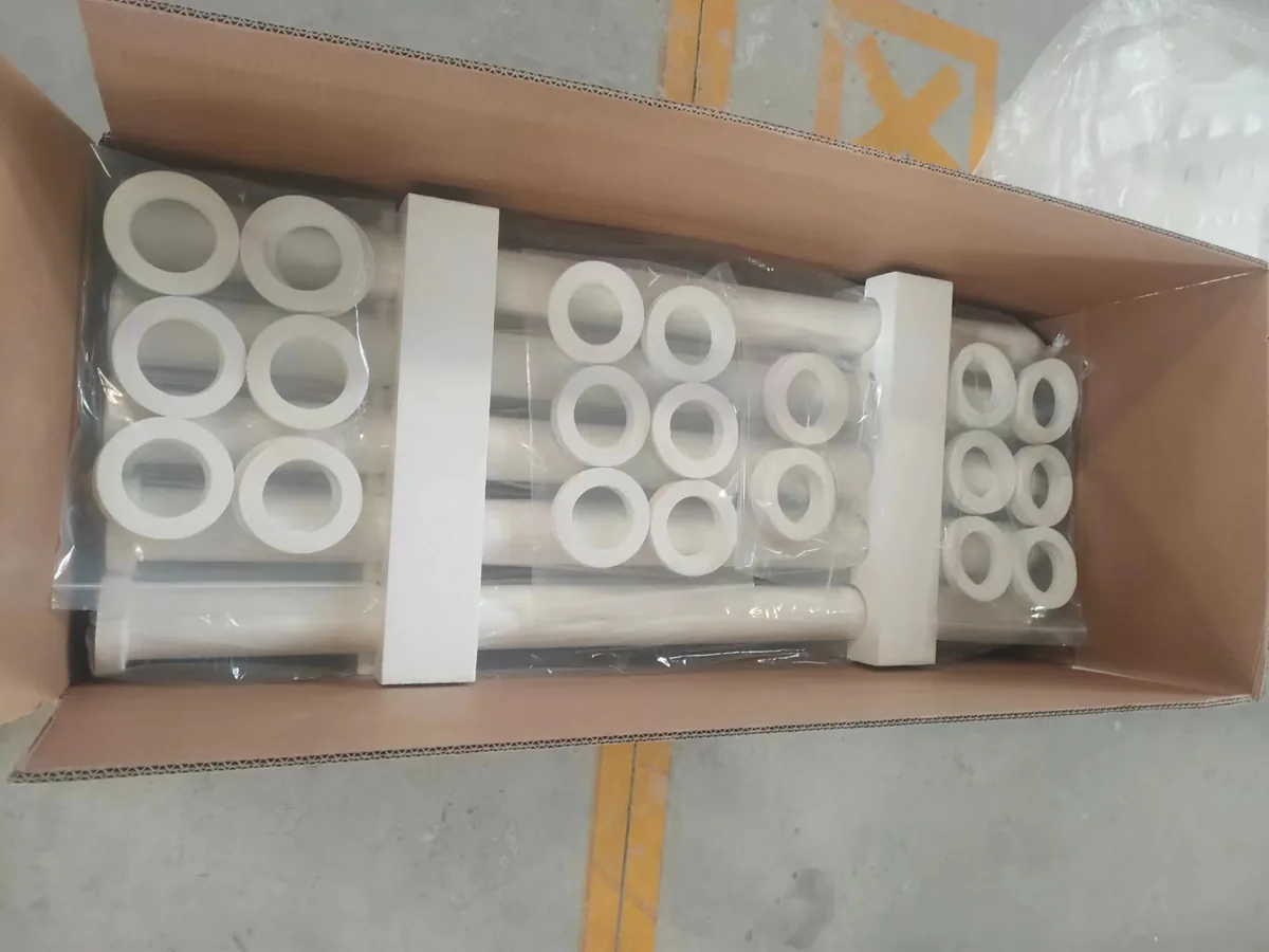
| Item | Specification | Notes |
|---|---|---|
| Dimensions | Ø150 × Ø110 × 3,000 mm | 20 mm wall |
| Unit weight | 7.5 kg (batch tolerance <0.5 kg) | White tube |
| Forming process | Integrated vacuum negative-pressure forming | European process |
| Porosity | >80% | |
| Fiber blend | 70% domestic + 30% imported fiber | |
| Initial pressure drop | 300 Pa | At 1 m/min filtration velocity, clean tube |
| Operating pressure drop | <1,500 Pa | Glass industry duty typically 900–1,300 Pa at 1 m/min |
| Breakage rate | <0.2% within 3 years | With correct installation; tubes virtually never snap in service |
| Service life (incl. fittings) | >5 years | Counted from 168-hour acceptance |
| Production capacity | 72,000 tubes / year | |
| Lead time | <60 days |
Material and performance envelope across the range:
| Property | Value |
|---|---|
| Chemistry | Al₂O₃ + SiO₂ >90% |
| Color | White / cream |
| Density | 300–400 kg/m³ |
| Temperature grades | 600 °C and 1,000 °C continuous-service grades; maximum use temperature 1,050 °C |
| Pore size range | 10–180 μm, graded through the wall |
| Compressive strength | >1,000 N |
| Impact resistance | >0.6 MPa |
| Max filtration velocity | 1.5 m/min |
| Typical particulate emission | <5 mg/Nm³ |
| Static resistance | 326 Pa |
| Max element size | 3,000 mm long × Ø150 mm, 1.4 m² filtration area per element |
| Captures | PM2.5 and sub-micron particles |
Sizes and Selection: 36 Standard Models

Standard elements cover lengths from 500 to 3,000 mm, outer diameters of 60 / 120 / 150 mm and inner diameters of 40 / 80 / 110 / 120 mm, with T-type or Y-type flanges. Filtration area runs from 0.2 to 1.4 m² per element and unit weight from about 0.4 to 9.5 kg.
Two build series are available: white non-catalyst tubes (AW series) and catalyst-loaded DeNOx tubes (AC series), both in ultra-high-temperature and end-reinforced builds.
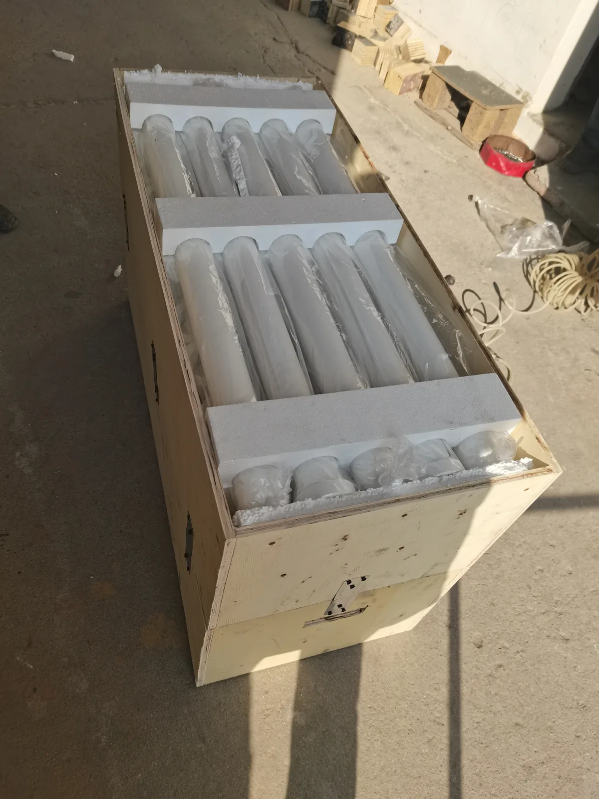
| Model (example) | Length mm | OD / ID mm | Flange | Area m² | Weight kg |
|---|---|---|---|---|---|
| AW500 | 500 | 60 / 40 | T | 0.2 | 0.4 |
| AW1000 | 1,000 | 150 / 110 | T | 0.48 | 3.2 |
| AW1250 | 1,250 | 60 / 40 | T | 0.23 | 0.8 |
| AW2000 | 2,000 | 150 / 110 | T | 1.0 | 5.0 |
| AW3000 | 3,000 | 150 / 110 | T | 1.4 | 8.5 |
| AW1950 | 1,950 | 150 / 110 | Y | 1.0 | 5.0 |
| AW2400 | 2,400 | 120 / 80 | T | 0.9 | 5.5 |
Full model list and selection logic: → Ceramic Filter Element Selection Guide
Catalyst-Loaded Tubes: DeNOx Verified by the CAS Process Institute

Catalyst performance was tested by the State Key Laboratory of Multiphase Complex Systems, Institute of Process Engineering, Chinese Academy of Sciences, on Ø60 × 50 mm (10 mm wall) catalyst tube samples. Test conditions: face velocity 0.5–0.8 Nm/min (working-face velocity 0.9–1.8 m/min), inlet NO 700 ppm (1,400 mg/Nm³), ammonia-to-NOx molar ratio 1, 170–450 °C, with 300 ppm SO₂ (900 mg/Nm³) and 10 vol.% H₂O in the sulfur/water cases.
Mid-temperature catalyst tube: in sulfur- and water-free gas, DeNOx approaches the theoretical rate from 240 °C. With 900 mg/Nm³ SO₂ and 10% water vapor present, low-temperature activity drops, but above 280 °C water and SO₂ have little effect. Recommended operation at 280 °C or above; below 280 °C, keep SO₂ under 35 mg/Nm³ for long-cycle running.
Low-temperature catalyst tube: in sulfur- and water-free gas it reaches 90% DeNOx at 180 °C and approaches the theoretical rate from 200 °C. With SO₂ and H₂O present it still holds 80% at 180 °C and exceeds 90% at 200 °C. Recommended operation at 180 °C or above to avoid water condensation; for long service life keep SO₂ within 5–30 mg/Nm³.
Both tubes are applicable to glass furnaces, biomass power, waste incineration, hazardous waste and coking flue gas. → Low-Temperature DeNOx: How Catalytic Ceramic Filters Work at 170–300 °C · → Catalytic Ceramic Fiber Filter product page
Strength, Service Life and Verification
A third-party test to GB/T 3002-2017 (refractories — hot modulus of rupture) measured a hot bending strength of 1,016.14 N at 600 °C. Combined with the >1,000 N compressive rating, this is why breakage stays below 0.2% over three years when installation rules are followed — and why filter life is counted in years, not bag-change cycles. Catalyst-loaded tubes carry a 7–9 year catalyst service life with 5 years guaranteed.
Non-catalyst version: → Non-catalyst Ceramic Fiber Filter
Where Hot Gas Filtration Is Already Working

- Ultra-high-temperature filtration: fumed silica and alumina production, converter off-gas, metal smelting, chemical processes
- SCR DeNOx: glass furnaces, biomass and wood-waste firing, waste-to-energy plants
- Acid gas–solid separation and acid recovery: hydrochloric and sulfuric acid duty
- Combustible gas cleaning: municipal waste and biomass biogas
- Heavy and precious metal recovery: uranium, nickel, cobalt, lithium, gold, silver, palladium, platinum and their oxide residues
Documented installations include glass furnaces in Spain and Costa Rica, medical waste incinerators and metal melting furnaces. → Applications · → Dioxin Removal from Waste Incinerator Flue Gas

Commissioning and Operation Essentials
Ceramic tubes run differently from bags in one respect: commissioning matters. The documented procedure:
- Binder burn-out — heat the gas through the elements slowly to 160 °C and hold 160–170 °C for 16 hours to decompose the organic binder safely.
- Pre-coating — dose preconditioning powder (e.g. agricultural lime, talc, SiO₂, Al₂O₃ or class-1 fly ash) to build a 200 g/m² protective layer; about 40 g per 1,000 mm element or 300 g per 3,000 mm element, repeated for at least three full cleaning cycles.
- Pulse cleaning — never pulse at or below the dew point; clean between upper and lower ΔP limits and avoid over-cleaning, which is as harmful as under-cleaning. Stable ΔP is normally reached within 24–48 hours.
- Monitoring — watch the outlet with a triboelectric probe or opacity meter; anything above 5 mg/Nm³ (or above the usual level) signals a leak to trace back to its module. Fluorescent powder with UV light pinpoints seal leaks.
- Shutdowns — keep the unit above 120 °C during shutdown to prevent condensation, seal inlet and outlet against moisture, and repeat the full commissioning procedure after long stops.
→ Pre-coating Ceramic Filter Tubes: Why It Matters and How to Do It · → Installation and Fluorescent Leak Detection Step by Step
What to Send with Your RFQ
To size a unit or quote replacement elements, send: gas flow (Nm³/h), operating and peak temperature, dust loading and dust chemistry, acid gas / NOx / dioxin concentrations and emission targets, available footprint and tubesheet layout (for retrofits), and compressed air availability. Element drawings, flange type (T/Y) and quantity speed up replacement quotes.