
Good ceramic filter element selection is three calculations and one chemistry check, and most specifications get the order wrong: they pick a size, then discover the gas does not fit the material. This guide works the other way round. Read the stream first, then convert gas volume into element count using the standard φ150 × φ110 × 3,000 mm geometry, then build the pressure-drop budget against your fan, then screen the chemistry against the four boundaries that decide whether the element survives. Every number below is one you can put into an enquiry.
Step 1: Read the gas stream before the catalogue
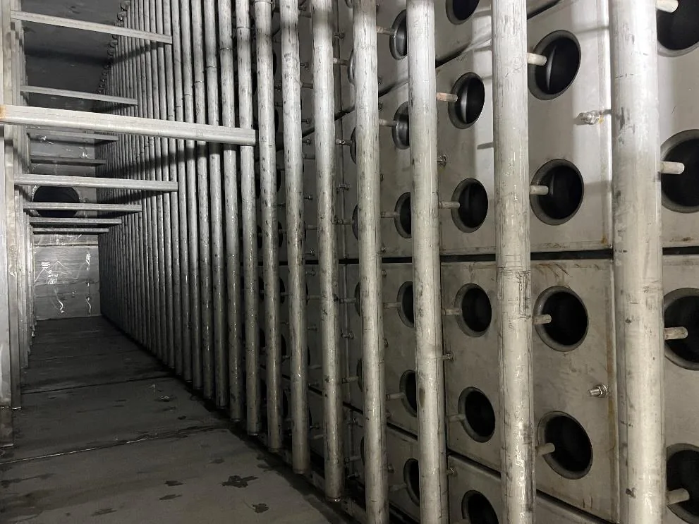
Four stream properties drive everything else: temperature profile, dust loading, moisture and acid or alkali content. Record the continuous temperature, the peak and how long peaks last, because a ceramic element rated for 600°C continuous and 1000°C peak still needs a controlled ramp to avoid thermal shock. Record dust loading in g/m³ and the particle size distribution, since fine sticky dust pushes you to the lower end of the velocity band. Record moisture, because above 20% by volume capillary condensation will mask itself as blinding. And record the species that matter chemically — HF, H₃PO₄, free alkali and SO₂.
Step 2: Geometry, area and element count
What the standard element gives you
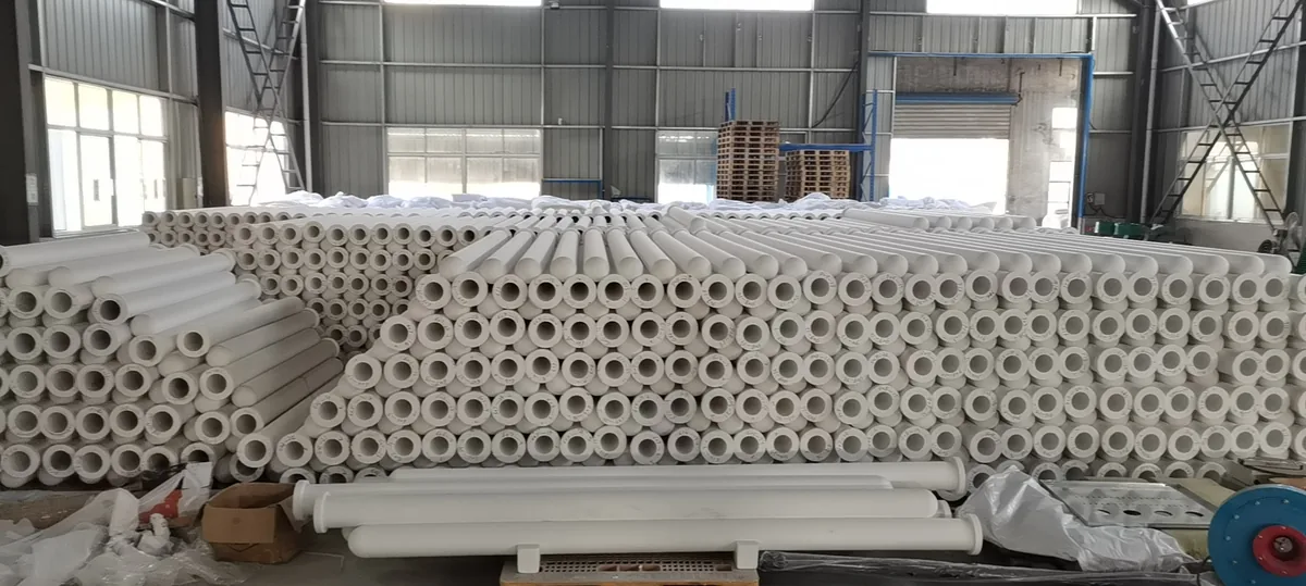
The standard candle is φ150 × φ110 × 3,000 mm with a 20 mm wall and porosity >80%. Manufacturing tolerance is OD ±2 mm and length ±20 mm, and both belong on your purchase order, because the hold-down and tubesheet design depend on them. The porosity figure is not a curiosity: above 80% open pore is what allows the element to hold 300 Pa at 1 m/min face velocity (clean) while still carrying its own weight and the pulse load at temperature. Filtration area comes from the outer surface — roughly 1.41 m² per standard element — and that is the number you divide into your gas volume. Confirm against the published element dimensions before you commit a layout.
Converting gas volume into an element count
Design the face velocity at 2–5 cm/s, which is about 1.2–3.0 m³/min per m². Divide the actual gas volume at operating temperature by the chosen velocity to get filter area, then divide by 1.41 m² to get the element count. The table below shows the spread for a 60,000 m³/h stream; the point is how much vessel size you trade for pressure drop and, in catalytic duty, for residence time inside the wall.
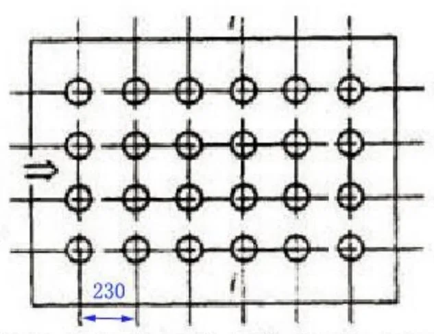
Always round the count up, then lay it out on the tubesheet before you accept it. A count that is correct on paper can still fail on pitch: elements need enough spacing for the pulse jet to travel to the closed end and for one person to lift a candle out without touching its neighbours. Check the peak, not just the average, gas volume as well — if a process upset doubles the flow for ten minutes each cycle, size for the upset or specify a bypass, because the element will not forgive it.
Handling weight is part of the same calculation. A standard non-catalytic candle weighs about 7.5 kg, and the catalytic version about 8.5 ± 0.5 kg, which sets the lifting method, the packing specification and the number of people you need for a changeout. Ask for elements packed with the seal faces protected; most transport damage arrives at the end of the candle, not in the wall.
| Design velocity | Equivalent loading | Filter area needed | Approx. elements (60,000 m³/h) |
|---|---|---|---|
| 2.0 cm/s | 1.2 m³/min per m² | 833 m² | 590 |
| 2.5 cm/s | 1.5 m³/min per m² | 667 m² | 472 |
| 3.0 cm/s | 1.8 m³/min per m² | 556 m² | 393 |
| 4.0 cm/s | 2.4 m³/min per m² | 417 m² | 295 |
| 5.0 cm/s | 3.0 m³/min per m² | 333 m² | 236 |
Rule of thumb: choose the lower half of the band for fine or sticky dust, for catalytic duty where residence time matters, and whenever your dust loading is high enough that the cake, not the element, will dominate resistance. Choose the upper half only when vessel footprint is the binding constraint.
Step 3: Build the pressure-drop budget
Do not hand the fan vendor a single number. A clean element is 300 Pa at 1 m/min face velocity (clean); the complete system settles between 900 and 1,500 Pa, with 900–1,300 Pa typical in glass furnace duty. Split the budget so that when resistance drifts you know which contribution moved. Remember that the clean figure is quoted at 1 m/min and scales with velocity, so a vessel running near the top of the band starts higher before any dust arrives.
| Contribution | Design value | Comment |
|---|---|---|
| Clean element at reference velocity | 300 Pa at 1 m/min face velocity (clean) | Scales with the chosen face velocity |
| Dust cake and residual layer | 250–500 Pa | Set by cleaning frequency and dust stickiness |
| Tubesheet, plenum and element support | 150–300 Pa | A layout problem shows up here first |
| Ducting, damper and hopper | 200–400 Pa | Usually inherited from the existing plant |
| Total system resistance | 900–1,500 Pa (900–1,300 Pa glass furnace) | Confirm against the ID fan curve with margin |
Then decide how you will read the trend, because that is what the budget is for. A slow rise in the floor after cleaning means the cake is not releasing, which points at moisture, at ABS, or at a pulse that is too short. A step change means a broken element or a failed seal. A falling resistance together with rising stack emissions almost always means a sealing or tubesheet problem rather than a media problem, and it is the one condition that spare elements will not fix.
Step 4: Chemistry — the boundaries that decide survival
This is the step that voids warranties when it is skipped. Sustained HF above 5 ppm attacks the fibre bond. Phosphoric acid (H₃PO₄) mist is excluded from the duty outright. Free Na₂O or K₂O alkali will flux the surface at temperature unless an alkaline sorbent is dosed upstream. Where a catalytic section operates below 280°C, SO₂ must stay under 35 mg/m³. Moisture stays below 20% by volume. Each of these is checkable before purchase, and each is far cheaper to fix upstream than to argue about afterwards.
| Component | Boundary | Why it matters |
|---|---|---|
| HF | Below 5 ppm sustained | Attacks the fibre bond and shortens element life |
| H₃PO₄ mist | Excluded | Reacts with the fibre phase; no safe operating band |
| Na₂O / K₂O | Only with alkaline sorbent present | Free alkali fluxes the surface at temperature |
| SO₂ below 280°C | Under 35 mg/m³ | Bisulphite condensation and catalyst masking |
| Moisture | Below 20% by volume | Capillary condensation reads as blinding |
| ABS deposits | Regenerate at 350°C for 12 h periodically | Decomposes the deposit and restores baseline resistance |
Get the chemistry confirmed by analysis rather than by process description. A material safety sheet or a design basis from five years ago is not a gas analysis, and the species that cause trouble — HF, phosphoric mist, free alkali — are rarely the ones a process engineer volunteers. Sample at the filter inlet, at operating temperature, and repeat the sample in the worst season, because moisture and acid dew point move with ambient conditions and with fuel or raw-material changes.
Where ammonia slip is present in the same temperature band, ammonium bisulphite is inevitable rather than optional. Treat it as a maintenance cycle: plan regeneration at 350°C for 12 hours at an interval set by the slip rate, and log the differential pressure before and after so you can see whether the interval is right.
Step 5: Temperature and whether you need catalysis
If the requirement is filtration only, the non-catalytic ceramic fibre filter elements run continuously at 600°C and survive peaks to 1000°C, which covers kilns, furnaces and most metallurgical streams without any cooling stage. If the requirement includes NOx or dioxins, the catalytic ceramic fibre filter elements work in a 170–300°C window with the optimum at 220–260°C: about 90% DeNOx at 200°C and about 98% at 280°C with the low-temperature formulation, and dioxin destruction up to 99.5% (TEQ) by selective catalytic oxidation. Dust collection stays above 99.9% in either case. The mistake to avoid is specifying catalytic elements for a stream that only enters the window during upsets.
Step 6: Cleaning air, life and warranty
Cleaning air and differential pressure control
Specify 0.4–0.7 MPa of dry, oil-free compressed air, a pulse duration of 0.1–0.15 s, and differential-pressure triggering rather than a fixed timer. The pulse is short because the element is rigid: it releases the cake by shock, not by flexing. Size the receiver so a full cleaning sequence completes without the header falling below 0.4 MPa, and make sure the triggering transmitter is on the clean side with a logged trend, because it is both the control input and the condition monitor for the next five years.
Life, warranty and spares
Service life is more than 5 years, backed by a 5-year written warranty, so the commercial question is not replacement frequency but what the warranty actually measures: document the clean baseline at commissioning and keep it with the warranty record. Hold enough spare elements to replace a row, since individual candles are replaceable and the realistic loss mechanism is handling damage rather than wear. Anchor Filter has been manufacturing these elements since 2019 and has delivered 40+ projects; the inspection routine we apply before shipment is described on our quality and inspection page.
Frequently asked questions
How do I convert my gas volume into a number of ceramic filter elements?
Divide the operating gas volume by your design velocity of 1.2–3.0 m³/min per m² to get filter area, then divide by the outer area of one standard φ150 × φ110 × 3,000 mm element, about 1.41 m². For 60,000 m³/h at 1.5 m³/min per m² that is roughly 667 m², or about 472 elements. Always round up and then check the count against the tubesheet pitch.
What clean pressure drop should go into the fan datasheet?
Quote 300 Pa at 1 m/min face velocity (clean) for the element and 900–1,500 Pa for the complete system including ducting and hopper, with 900–1,300 Pa typical in glass furnace duty. Because the clean figure is referenced to 1 m/min, scale it to your actual design velocity before adding the rest of the budget, and confirm the fan still has margin at the top of the range.
Which chemical components disqualify a ceramic element?
Sustained HF above 5 ppm, any phosphoric acid mist, and free Na₂O or K₂O alkali without an alkaline sorbent upstream. In catalytic duty below 280°C, SO₂ above 35 mg/m³ and moisture above 20% by volume are also outside the envelope. All four are fixable upstream with sorbent dosing, gas conditioning or better insulation — they are not reasons to abandon the technology.
Catalytic or non-catalytic: how do I choose?
Choose on the gas temperature and the permit. Non-catalytic elements handle 600°C continuously and 1000°C peak. Catalytic elements only work in the 170–300°C window, optimum 220–260°C, but they add about 90% DeNOx at 200°C, about 98% at 280°C and dioxin destruction up to 99.5% (TEQ). If your stream cannot hold the window, buy non-catalytic and treat NOx separately.
What tolerances and inspection items belong on the purchase order?
State the geometry as φ150 × φ110 × 3,000 mm with a 20 mm wall and porosity >80%, and the tolerances as OD ±2 mm and length ±20 mm. Add the clean pressure drop acceptance of 300 Pa at 1 m/min face velocity (clean), a visual and dimensional check on delivery, and packing that protects the element ends, since most transport damage occurs at the seal face rather than in the wall.
Send us your gas volume, temperature profile and gas analysis and we will return an element count, a pressure-drop budget and a chemistry screen for your stream — request a selection calculation.
 English
  Deutsch
  简体中文
简体中文  한국어
한국어  日本語
日本語  Español
  Français
  Italiano
  Türkçe
  Tiếng Việt
  Português
  हिन्दी
  العربية
  Polski
  繁體中文
繁體中文