
A low temperature denox catalytic filter removes NOx in the same vessel that removes dust, and it does so at the temperature the flue gas already has. That second point is the entire argument. Conventional SCR forces a plant to reheat the gas before it can remove NOx; a catalytic ceramic filter simply works where it is, which removes a heat exchanger, a burner bill and a great deal of ducting from the project.
None of this makes low-temperature DeNOx simpler than the alternative, though. Working between 170°C and 300°C brings its own set of boundaries — sulphur, moisture, ammonium bisulphate and absorbent quality all behave differently down there, and every one of them has a number attached. This article sets out how the catalyst works in that window, what it delivers, and the operating limits that keep it working for more than 5 years.
Why conventional SCR makes you pay for heat
Most SCR catalysts only become properly active above roughly 300°C. Below that, the reaction rate collapses, ammonia slip climbs, and the catalyst starts to suffer from the very species it is supposed to tolerate. The standard answer is to put the SCR reactor where the gas is still hot — which constrains the layout — or to install it at the tail end and reheat the gas to get there.
Reheating is expensive in a way that is easy to underestimate at the proposal stage. You are paying for fuel or steam every hour of every day to raise the temperature of the entire gas volume by a hundred degrees or more, and then you are paying again to recover or reject that heat downstream. On a mid-sized line this is a permanent operating cost attached to an emission requirement.
Tail-end arrangements also add a vessel, a catalyst bed, its own ducting and its own pressure drop. The plant ends up with a de-dusting step and a separate DeNOx step, each with its own footprint, its own instrumentation and its own maintenance window.
Where the catalyst sits inside a ceramic filter tube
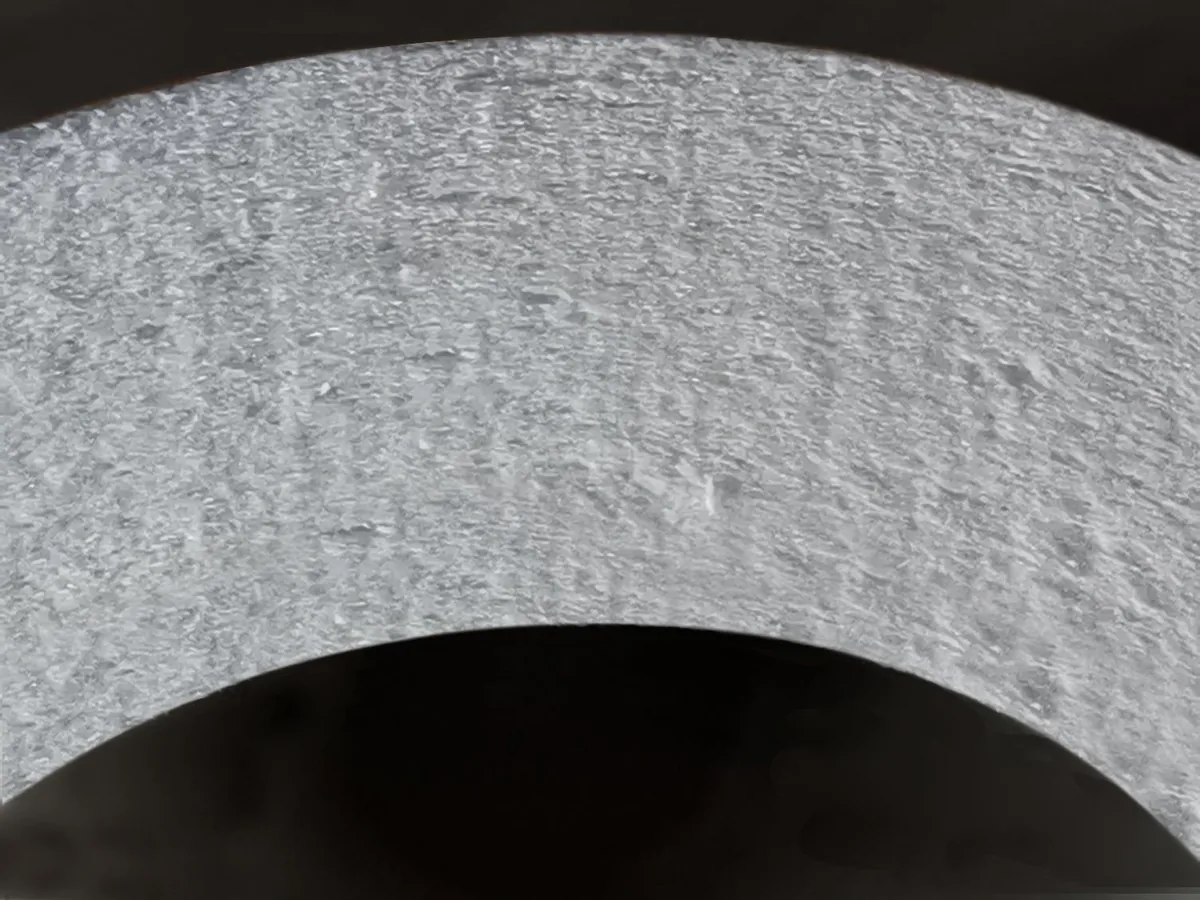
A catalytic ceramic fibre filter tube integrates the catalyst into the wall of the element itself. Gas flows from outside to inside, dust is rejected at the outer surface and in the near-surface pore structure, and NOx is reduced as the gas passes through the catalytically active wall. Dust removal and DeNOx happen in one pass through one component.
That integration matters for two reasons. First, the catalyst is protected behind the dust cake rather than exposed to a raw, abrasive gas stream, which is why catalyst life in this configuration is not the consumable cost it is in a conventional reactor. Second, the plant gets one vessel instead of two: no separate reactor, no reheat, no intermediate ducting, and one pressure drop instead of two.
It is worth separating two temperature ratings that are often confused. The ceramic body itself is rated for continuous 1100°C and short excursions to 1300°C for up to 30 minutes — it is the most temperature-tolerant part of the system. The catalyst is the temperature-sensitive component, and its reaction window is what sets where the vessel can sit in the process.
The 170–300°C window, and why 220–260°C is the sweet spot
The catalyst has a reaction window of 170–300°C. The best balance of activity, stability and resistance to deposits sits between 220°C and 260°C, and that is the band we design towards wherever the process allows it.
| Flue gas temperature | DeNOx efficiency | Operating note |
|---|---|---|
| 170°C | Lower end of the reaction window | Short excursions only; keep SO₂ and moisture tightly controlled |
| 200°C | 90% | Acceptable steady operating point |
| 220–260°C | Optimum band | Target range for design |
| 280°C | 98% and above | Watch SO₂ against the low-temperature limit |
| 300°C | Upper end of the reaction window | Deposit risk falls away as temperature rises |
Read that table as a design envelope rather than a performance curve you can dial. Efficiency at 200°C is 90%; at 280°C it is 98% or better. Both are workable numbers, and the choice between them is made on where the gas actually is and on how much sulphur and moisture the stream carries, not on chasing the last few percent.
Below 170°C the reaction rate falls away and ammonia slip rises sharply, which is a problem in its own right because unreacted ammonia is what feeds ammonium bisulphate formation further downstream. Above 300°C you are no longer in low-temperature territory, and the sulphur and deposit constraints described below ease considerably.
What “no reheat” actually saves
The saving is not abstract. Removing the reheat step takes out the following, and each line is a line on both the capital budget and the operating budget:
- Fuel or steam. No continuous energy input to raise the whole gas volume by 100°C or more before the catalyst.
- A vessel and its foundations. One filter housing instead of a filter plus a separate SCR reactor.
- Ducting, expansion joints and insulation. The runs between the reheater, the reactor and the stack disappear.
- Fan power. One system resistance of 900–1,500 Pa rather than two pressure drops in series.
- Outage hours. One vessel to inspect instead of two, and one spare-parts inventory instead of two.
There is a subtler saving as well. Because the catalyst sits inside the filter element, the de-dusting step protects it. In a conventional tail-end layout, the catalyst is downstream of the particulate control device and is exposed to whatever that device lets through, including the fine, alkali-rich fraction that poisons catalyst surfaces fastest.
The sulphur boundary: SO₂ below 280°C
Low-temperature DeNOx is not a free lunch. The same chemistry that lets the catalyst work at 200°C also makes it sensitive to sulphur, and that sensitivity has a hard number attached to it.
When the filter operates below 280°C, SO₂ in the flue gas should be held below 35 mg/m³. Below 230°C it has to be lower still. Those are the boundaries we specify, and they are not conservative padding — they are where ammonium bisulphate formation starts to outrun the plant’s ability to remove it.
Moisture is the other half of the same problem. The gas must stay above its dew point, and the moisture content must not be allowed to run high. Condensation on a catalytic element does two things at once: it drives the acid and sulphur species into the pore structure, and it turns the dust cake into a paste that will not release at cleaning.
Keep SO₂ below 35 mg/m³ when running under 280°C, lower again below 230°C, keep the gas above its dew point, and do not let moisture content run high. Those four conditions are what make 170–300°C operation sustainable.
Ammonium bisulphate: the deposit you have to design around
Ammonium bisulphate — ABS — is a gel-like particulate that forms at low temperature from ammonia, sulphur trioxide and water vapour. It is the single most important reason low-temperature DeNOx has operating rules attached to it, because it attacks the element from both sides at once: it blocks the pores of the filter tube, and it coats the catalyst so the NOx reaction loses active surface.
- Rising differential pressure that is out of proportion to the dust load — the pores are being blocked from the inside.
- Falling DeNOx efficiency while ammonia consumption rises — the catalyst is being masked rather than poisoned, which is good news, because masking is reversible.
- A dust cake that has hardened and no longer releases cleanly at pulse-jet cleaning.
- Ammonia slip at the stack that was not there at start-up.
The control for ABS is thermal, and it has to be scheduled rather than reactive. The housing temperature must be raised above 350°C and held there for more than 12 hours on a regular basis, which decomposes the ammonium bisulphate that has accumulated and restores both the pore structure and the catalyst surface. Plants that treat this as optional discover the cost in differential pressure and in catalyst activity.
| What you observe | Likely cause | Action |
|---|---|---|
| Differential pressure rises faster than the dust load explains | ABS or moisture-driven caking inside the pore structure | Schedule thermal regeneration above 350°C for more than 12 hours |
| DeNOx efficiency falls while ammonia slip rises | Catalyst surface masked by ABS | Thermal regeneration; re-check SO₂ and moisture against their limits |
| Filter surface hardens and the cake will not release | Moisture and alkaline absorbent caking | Check absorbent moisture content and gas humidity; review continuous low-temperature run length |
| Stable pressure but steadily rising ammonia consumption | Catalyst activity declining | Confirm the housing is operating inside the 220–260°C band |
| Pressure and efficiency both drop after a wet start-up | Condensation on a cold element | Re-check dew point margin and heat-up procedure |
Plan the regeneration into the outage calendar. It needs a heat source capable of holding the housing above 350°C and enough time for the hold, so it belongs in the annual shutdown plan rather than being improvised when the pressure trend turns.
Moisture, absorbent quality and the risk of surface caking
Two numbers decide whether the tube surface stays friable or turns into a hard layer: the moisture content of the calcium hydroxide used for dry deacidification, and the moisture content of the flue gas itself.
If the Ca(OH)₂ moisture content is above 0.8%, or the flue gas moisture content is above 20%, and the plant then runs for more than 12 continuous hours below 270°C, the surface of the filter tube will cake and harden and the resistance will climb. Those three conditions are cumulative — any one of them alone is survivable, and all three together produce a tube that has to be cleaned or replaced.
- Store hydrated lime dry. Delivery and storage moisture is the most common cause of the problem, and it is entirely preventable.
- Keep the vessel above its dew point at all times, including during start-up and standby.
- Limit continuous running below 270°C where the process allows it, and trend how long each low-temperature run lasts.
- Trend differential pressure against temperature and humidity together, not in isolation. The combination is what causes caking; the pressure alone only tells you it has happened.
Our published performance data shows the pressure and efficiency curves for elements operated inside these boundaries. Data from plants that have drifted outside them looks very different, and the difference is visible in the trend long before it shows in the stack reading.
Why sodium bicarbonate and hydrated lime are used together below 300°C
Dry deacidification behaves differently below 300°C than it does in a hot duct, and the standard single-sorbent approach is usually the wrong one here. Sodium bicarbonate reacts faster in the gas phase and holds its reactivity at lower temperature; hydrated lime is cheaper per tonne and carries better over the longer residence time the filter cake provides.
Used together, they cover each other’s weaknesses. Bicarbonate handles the fast reaction during the short residence time in the duct; hydrated lime continues reacting in the filter cake, where the gas is in contact with the sorbent for far longer. The practical result is a higher deacidification efficiency at a lower total sorbent cost than either material achieves alone at this temperature.
- Sodium bicarbonate — fast gas-phase reaction, effective at low temperature, higher unit cost.
- Hydrated lime, Ca(OH)₂ — lower unit cost, slower, continues reacting in the cake; must be stored below 0.8% moisture.
- Combined — better acid removal at low temperature with a lower combined cost, and a filter cake that stays friable.
The combination also helps the ABS problem indirectly. Better deacidification upstream means less SO₃ reaching the catalyst, which means less ammonium bisulphate to remove at the next thermal regeneration.
Chemistry limits to check before specifying
Three chemical boundaries should be screened before any low-temperature catalytic element is specified. They are not preferences; outside them, the catalytic grade is the wrong product:
- HF above 5 ppm. Fluorine attacks the ceramic fibre structure itself, independent of the catalyst.
- Phosphoric acid mist (H₃PO₄). Acid mist condenses in the pore structure and is not removed by pulse-jet cleaning.
- Na₂O and K₂O where no alkaline absorbent is injected ahead of the filter. Without an alkaline absorbent to tie them up, alkali oxides attack the fibre at temperature.
Where any of those three apply, specify a non-catalytic ceramic fibre filter tube for the particulate duty and handle NOx separately, or treat the chemistry upstream first. Trying to run a catalytic element outside these limits buys a short campaign and a re-tube.
Mechanical and operating envelope
| Parameter | Value |
|---|---|
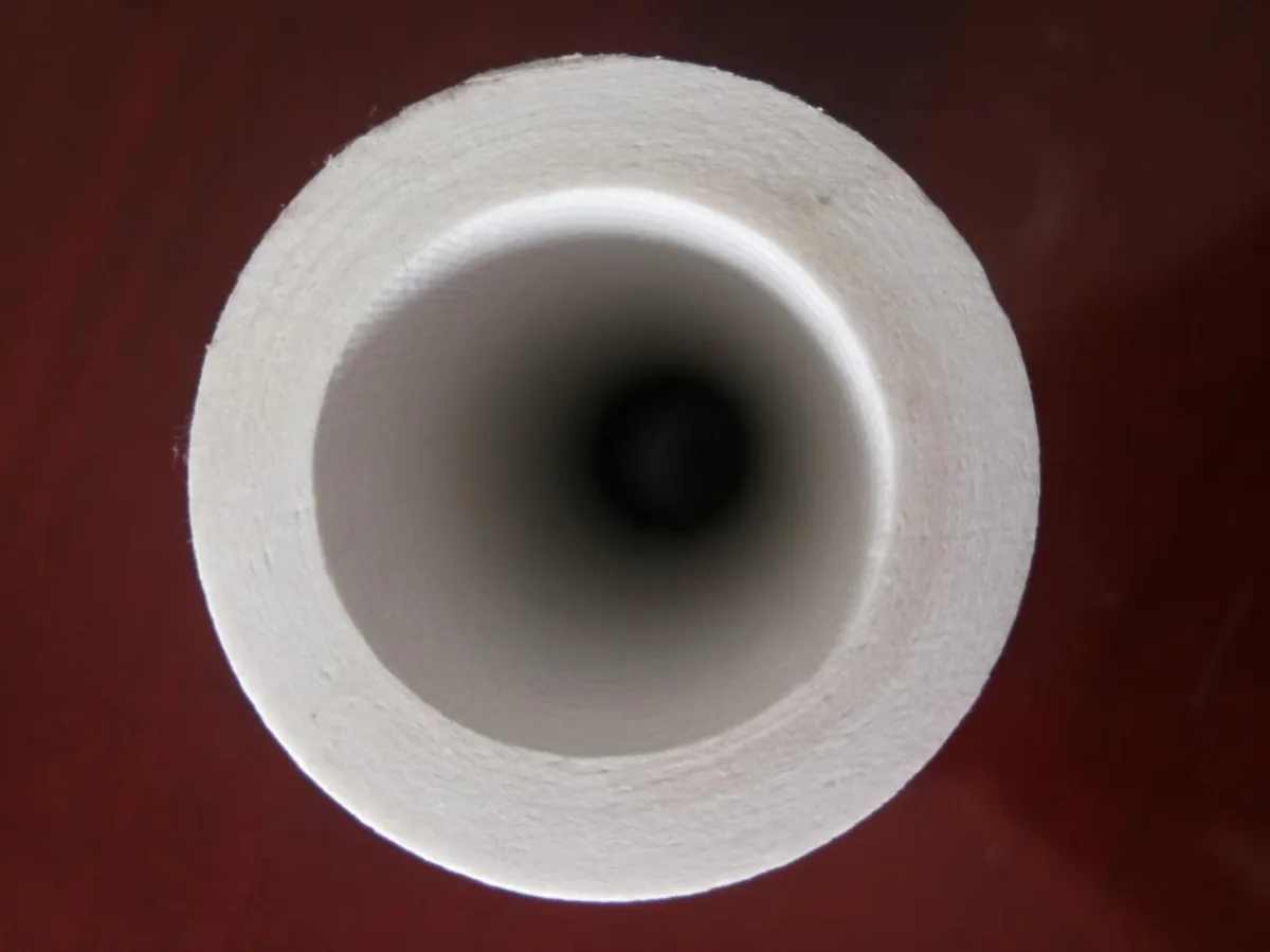
| Standard element | φ150 × φ110 × 3,000 mm, wall thickness 20 mm |
| Dimensional tolerance | OD ±2 mm / length ±20 mm |
| Porosity | >80% |
| Temperature resistance | Continuous 1100°C; short-term 1300°C for up to 30 min |
| Catalyst reaction window | 170–300°C, optimum 220–260°C |
| Filtration velocity | 2–5 cm/s (≈1.2–3.0 m³/min per m²) |
| Initial pressure drop | 300 Pa at 1 m/min face velocity (clean) |
| System resistance | 900–1,500 Pa |
| Cleaning | 0.4–0.7 MPa, 0.1–0.15 s, triggered by differential pressure |
| Filtration efficiency | >99.9% |
| Dioxin removal | up to 99.5% (TEQ) |
| Design life | more than 5 years, backed by a 5-year written warranty |
Full dimensional and material options are listed on our products page. Note that the temperature resistance line and the catalyst window describe two different things: the ceramic body will take 1100°C continuously, while the catalyst determines where in the process the vessel can usefully sit.
Where this configuration is running
We have supplied ceramic filtration since 2019 and have delivered 40+ projects across waste incineration, cement, biomass and metallurgical duty. Two references are representative of the low-temperature and high-temperature ends of the range:
- Guangzhou Nansha — 750 t/d municipal waste incineration line, where dust, acid gases, dioxin and NOx are handled in a single filter housing.
- Shandong — 2,500 t/d cement clinker line, commissioned in 2019 and still in service, which is where the “more than 5 years” claim comes from rather than from an accelerated test.
Further installations by sector are summarised on our applications page. If your process sits somewhere between those two, the useful question is not whether ceramic filtration works there but which of the boundaries above governs the design.
Operating checklist for low-temperature DeNOx
- Hold the housing in the 220–260°C band wherever the process allows it.
- Keep SO₂ below 35 mg/m³ when operating below 280°C, and lower still below 230°C.
- Keep the gas above its dew point at all times; do not let moisture run high or condense.
- Check calcium hydroxide moisture content and keep it at or below 0.8%.
- Limit continuous operation below 270°C to under 12 hours wherever possible.
- Schedule thermal regeneration: housing above 350°C, held for more than 12 hours.
- Combine sodium bicarbonate with hydrated lime for low-temperature deacidification.
- Trend differential pressure, temperature and ammonia slip together, not separately.
Frequently asked questions
What is the actual reaction window of a low temperature denox catalytic filter?
170–300°C, with the optimum band between 220°C and 260°C. Efficiency is 90% at 200°C and 98% or better at 280°C. Above 300°C you are back in conventional SCR territory; below 170°C the reaction rate falls off and ammonia slip climbs.
Why does the housing have to be heated above 350°C periodically?
To decompose ammonium bisulphate. ABS forms as a gel-like particulate at low temperature from ammonia, SO₃ and water vapour; it blocks the pores of the tube and coats the catalyst. Raising the housing above 350°C and holding it there for more than 12 hours breaks it down and restores both filtration and catalytic activity.
What happens if SO₂ runs above 35 mg/m³ at low temperature?
ABS formation accelerates, which shows up first as differential pressure rising faster than the dust load explains, then as falling DeNOx efficiency and rising ammonia slip. Corrective action is to bring SO₂ back under 35 mg/m³ below 280°C — lower still below 230°C — and to run a thermal regeneration above 350°C.
Can the filter run below 170°C at start-up?
Briefly, yes — the ceramic body is unaffected — but the catalyst is not doing useful work there and ammonia slip will be high. Bring the housing into the window before injecting ammonia at full rate, and keep the vessel above its dew point throughout the heat-up.
How do absorbent moisture and flue gas moisture affect the element?
If Ca(OH)₂ moisture content exceeds 0.8%, or flue gas moisture exceeds 20%, and the plant then runs more than 12 continuous hours below 270°C, the tube surface cakes and hardens and resistance climbs. Store hydrated lime dry, keep the gas above dew point, and watch how long each low-temperature run lasts.
Is a separate SCR reactor still needed downstream?
Usually not. With dust removal at >99.9%, dioxin removal up to 99.5% (TEQ) and DeNOx in the same element, the catalytic ceramic filter replaces the particulate device and the SCR reactor in a single housing. It is only where the stream breaks one of the chemical boundaries — HF above 5 ppm, phosphoric acid mist, or alkali without an alkaline absorbent — that a separate arrangement is the better answer.
Evaluating low-temperature DeNOx for your line? Send us your gas volume, temperature profile, SO₂ and moisture figures, and our engineers will confirm whether the 170–300°C window suits your process and where the vessel should sit. Request a DeNOx feasibility review.
 English
  Deutsch
  简体中文
简体中文  한국어
한국어  日本語
日本語  Español
  Français
  Italiano
  Türkçe
  Tiếng Việt
  Português
  हिन्दी
  العربية
  Polski
  繁體中文
繁體中文