
Catalytic Ceramic Fiber Filter
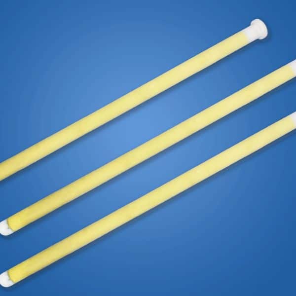
Product Description
Added the catalyst on the basis of the white filter can get catalytic ceramic fiber filter (catalytic candle filter), which is a porous filter integrated multi-functions of dedusting, desulfurization, denitrification, de-acid gas, and de-dioxin.
Its desulfurization and denitrification efficiency are up to 95%, far exceeding the national standards. And it can remove the dioxin directly.
Use it for denitrification and de-dioxin can not only greatly reduce the supporting equipment and the overall area of the whole system, but also the various kinds of supporting operation costs.
Product model and size specifications
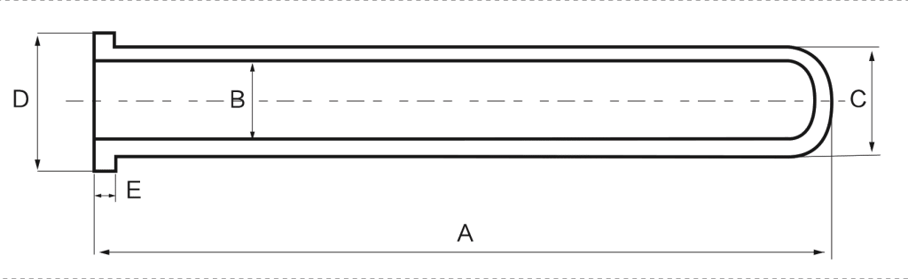
Catalytic elements are produced in the same AW model range and dimensions as our standard tubes — see the full model & dimension table on the performance page.
Illustration: Below is Ceramic fiber filter’s dimension diagram :
Application
Glass furnaces, steel furnace, biomass boiler, thermal power plant, waste incinerator, coking plant, metallurgical smelting furnace, etc.
For dedusting only, see our non-catalyst ceramic fiber filter. Contact us for a quotation.
Work efficiency
NOx<50mg/Nm3 SO2<30mg/Nm3 | Up to 97% HCL removal Up to 95% SOx removal Up to 95% NOx removal Up to 99.5% dioxin removal (TEQ) |
Remark: The removal rate of the pollutants in the flue gas depends on the performance of the additives, as well as the design, construction, and the operation level of the equipment.
Key Specifications
| Parameter | Value | ||
|---|---|---|---|
| Filtration accuracy | ≥ 1 μm (dust larger than 1 micron) | Max long-term operating temperature | 600 °C continuous / 1000 °C max (dedusting mode) |
| Filter resistance (room temperature) | 300 Pa (1 m/min, clean) | Whole dedusting system resistance | 900–1,500 Pa |
| Filtration (face) velocity | 2 – 5 cm/s | Backflush pressure | 0.4 – 0.7 MPa |
| Backflush duration / trigger | ≈ 0.15 s, pressure-difference triggered | Dedusting efficiency | >99.9% |
| Dust residual emission | < 5 mg/Nm3 | Service life | More than 5 years (5-year written warranty) |
| Operating mode | Pulse-jet cleaning, similar to baghouse layout | Physical strength | Maintains high strength at room and high temperature without keel reinforcement |
Source: Anchor Technology laboratory & field data. For project-specific selection consult our engineering team.
Proven DeNOx Performance in Waste Incineration & Biomass Applications
Anchor Technology’s catalytic ceramic fiber filters have been operating in waste-to-energy plants and biomass power stations across China and Southeast Asia since 2019. Our largest single installation (Guangzhou Everbright Nansha Waste-to-Energy Plant, 750 t/d MSW capacity) uses 240 catalytic filter tubes in a 6-module pulse-jet collector, processing 180,000 Nm³/h flue gas at 320°C. After 3.5 years of continuous operation, the system maintains 91% NOx reduction (from 400 mg/Nm³ inlet to 36 mg/Nm³ outlet) and <2 mg/Nm³ particulate emissions, well below the EU 2010/75/EU limit of 10 mg/Nm³ dust and 200 mg/Nm³ NOx.
The key advantage over separate baghouse + SCR systems is the elimination of the SCR catalyst poisoning problem. In traditional setups, dust-laden gas enters the SCR reactor and deposits alkali metals (Na, K) and heavy metals (Pb, Zn) on the catalyst surface, gradually blocking active sites. With our catalytic filters, dust is captured on the OUTER surface of the filter tube before it can contact the catalyst layer inside the porous wall — the catalyst sees only clean gas. This extends catalyst life from the typical 2–3 years (for dust-exposed SCR catalyst) to 5–7 years, and maintains stable DeNOx efficiency without the gradual performance degradation you’d see in a dusty SCR environment.
Chemical Compatibility
The alumino-silicate substrate shares the chemical compatibility envelope of our standard ceramic fiber filter tube (sustained HF below 5 ppm, no phosphoric acid mist, free alkali only with an alkaline sorbent dosed upstream). Catalytic duty adds three boundaries of its own: where the catalytic section runs below 280°C, SO₂ must stay under 35 mg/m³; moisture stays below 20% by volume; and ammonium bisulphate (ABS) deposits are managed by scheduled regeneration at 350°C for 12 hours.
Catalyst System & Operating Window
| Function | Performance | ||
|---|---|---|---|
| Catalyst substrate | Alumina + silica base ceramic fiber | Recommended operating window | 250 °C – 400 °C |
| Dedusting efficiency | >99.9% | SOx removal | up to 95% |
| NOx removal | up to 95% | Dioxin removal | up to 99.5% (TEQ) |
| HCL removal | up to 97% | Emission level (typical) | NOx < 50 mg/Nm3; SO2 < 30 mg/Nm3 |
| Integration benefit | Dedusting + DeSOx + DeNOx + dioxin removal in one vessel – eliminates downstream SCR tower and slurry system | ||
For full performance curves, see our Performance & Test Reports page.
For the dedusting-only grade built on the same substrate, see the ceramic fiber filter tube specification.
Catalyst Chemistry & Poisoning Resistance
Our V₂O₅-TiO₂ catalyst is formulated specifically for high-dust, high-sulfur environments. The TiO₂ support has a bimodal pore structure: micropores (2–10 nm) provide high surface area for the vanadium active sites, while mesopores (20–50 nm) allow gas diffusion deep into the catalyst layer. This structure resists pore plugging by fine dust particles and ammonium bisulfate (ABS) deposits that form when SO₃ reacts with excess NH₃ below 300°C. We also add 3–5% tungsten trioxide (WO₃) as a structural promoter, which reduces SO₂ oxidation to SO₃ (the precursor to ABS formation) from the typical 2–3% conversion rate down to <1%, significantly extending catalyst life in high-sulfur applications.
For processes with high alkali metal content in the fly ash (biomass combustion, some waste incineration streams), we offer an enhanced poisoning-resistant formulation with 8% WO₃ and proprietary alkali-trapping additives. This version has been field-tested in a straw-fired biomass boiler (35 MW, Jiangsu Province) with potassium-rich ash (12% K₂O in fly ash) and maintained >85% DeNOx efficiency after 18 months, compared to 65% efficiency with standard V-Ti catalyst under the same conditions. If your gas contains >5,000 ppm SO₂ or your fly ash has >8% alkali content, we recommend this enhanced formulation — contact our technical team with your fuel analysis and we’ll confirm the appropriate catalyst specification.
Catalyst Loading, Verified on Every Batch
The catalytic elements we supply are produced on dedicated ceramic fiber lines in Jiangsu, China, with catalyst impregnation and sintering in the same process chain. Catalyst loading (typically 8–15% V₂O₅ by weight) and coating penetration depth can be adjusted to match your specific gas composition and temperature profile — not a one-size-fits-all coating. Every batch is verified against specification before it ships: catalyst loading, filtration efficiency and mechanical strength.
On request, batch test documentation ships with your order: filtration efficiency per ISO 11057 (monodisperse NaCl aerosol at 1 μm) and DeNOx activity data from pilot-scale testing at your specified operating temperature. For orders over 200 pieces, we support commissioning remotely or on site — reviewing actual NOx reduction and pressure drop under your operating conditions and helping fine-tune the ammonia injection strategy.
Frequently Asked Questions About Catalytic Ceramic Fiber Filter Tubes
Technical Datasheet (PDF)
Download the complete technical datasheet for engineering selection: dimensional drawings, pressure-drop curves, model-to-cloth-area mapping, mechanical-load curves and chemical compatibility reference.
Request the PDF datasheet We will reply within 1 business day with the PDF and a sizing recommendation.
Common questions answered in our technical FAQ and working principle pages.
 English
  Deutsch
  简体中文
简体中文  한국어
한국어  日本語
日本語  Español
  Français
  Italiano
  Türkçe
  Tiếng Việt
  Português
  हिन्दी
  العربية
  Polski
  繁體中文
繁體中文