
A baghouse retrofit ceramic filter project is won during the survey, not during the installation. Most failed high temperature baghouse retrofits did not fail because the elements were wrong; they failed because nobody re-checked the tubesheet flatness, the fan margin or the acid dew point before the old bags came out. This checklist follows the order an EPC team actually works in: survey, chemistry screen, area recount, mechanical adaptation, pulse-air upgrade, commissioning and handover. Work through it before you issue a purchase order and the shutdown length becomes predictable.
Step 1 — Survey the gas before you touch the vessel
Collect at least 72 hours of logged data across a normal production cycle, including start-up and shut-down, not just steady state. You need the continuous temperature, the peak temperature and how long peaks last, oxygen content, moisture, dust loading in g/m³, particle size distribution and the full acid and alkali spectrum. Pay particular attention to how often the stream crosses its dew point, because that single fact decides whether you need casing insulation, a bypass flue or a heat-up procedure before every start.
Step 2 — Screen the chemistry against the hard boundaries
Ceramic fibre handles most mineral dusts and acidic gases, but four conditions sit outside the envelope. Sustained HF above 5 ppm attacks the fibre bond, phosphoric acid mist is excluded outright, and free Na₂O or K₂O alkali will flux the surface unless an alkaline sorbent is dosed upstream. Where a catalytic section runs below 280°C, SO₂ must stay under 35 mg/m³. Moisture should stay below 20% by volume. If any of these is breached, solve it upstream with sorbent injection or gas conditioning before you order elements.
| Boundary | Limit to design against | What to do if it is exceeded |
|---|---|---|
| HF | Keep sustained exposure below 5 ppm | Add or increase alkaline sorbent injection upstream; re-sample |
| H₃PO₄ mist | Excluded from the duty | Mist elimination or process change upstream of the filter |
| Na₂O / K₂O | Only with an alkaline sorbent present | Dose hydrated lime or sodium bicarbonate and confirm by analysis |
| SO₂ below 280°C | Keep under 35 mg/m³ | Raise the operating temperature or desulphurise upstream |
| Moisture | Below 20% by volume | Insulate and heat-trace the casing; keep the vessel above dew point |
Note: Ammonium bisulphite (ABS) is not a disqualifier, it is a maintenance item. Where ammonia slip is present, schedule periodic regeneration at 350°C for 12 hours to decompose the deposit and return the elements to baseline resistance.
Step 3 — Re-engineer the vessel: window, area and fan
Fix the operating window: 600°C continuous (1000°C peak) or 170–300°C
Decide now whether the vessel is a filter or a filter plus reactor. Non-catalytic elements run continuously at up to 600°C and tolerate peaks to 1000°C, which suits kilns, furnaces and any stream already far above fabric limits. Catalytic elements work in a 170–300°C window with the optimum at 220–260°C: about 90% DeNOx at 200°C and about 98% at 280°C with the low-temperature formulation, plus dioxin destruction up to 99.5% (TEQ). Dust collection stays above 99.9% in both cases. If you want catalytic performance today, the window dictates the gas path; if you might want it later, keep the temperature range in the design brief.
Recount filter area and element numbers
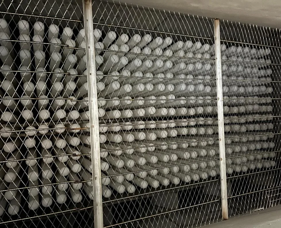
Do not carry the old bag count across. Recalculate from the design velocity of 2–5 cm/s (≈1.2–3.0 m³/min per m²). A standard φ150 × φ110 × 3,000 mm candle offers roughly 1.41 m² of outer filter area, so a 60,000 m³/h stream designed at 1.5 m³/min per m² needs about 667 m² of area, which is roughly 472 elements. Compare that with the number of bag cells you have; in most retrofits the answer is fewer candles than bags, and the freed space is where you put clearance for handling. Check the standard element range and dimensions before you finalise the layout.
Rebuild the pressure drop budget and check the fan
A clean ceramic element gives 300 Pa at 1 m/min face velocity (clean), and the complete system settles between 900 and 1,500 Pa, with 900–1,300 Pa typical in glass furnace duty. If the resistance behaves differently from what the filtration principle of a rigid ceramic body predicts, the cause is usually layout rather than media. Build the budget line by line: element, dust layer, tubesheet and plenum, ducting and damper, hopper. Then take it to the ID fan with the new gas volume. Because you are usually deleting the cooling air that kept the bags alive, the volume often falls at the same time as the resistance becomes more stable — but confirm the fan still has static margin at 1,500 Pa before the shutdown, not after it.
Step 4 — Mechanical and pulse-air work
Tubesheet, hold-down and clearance
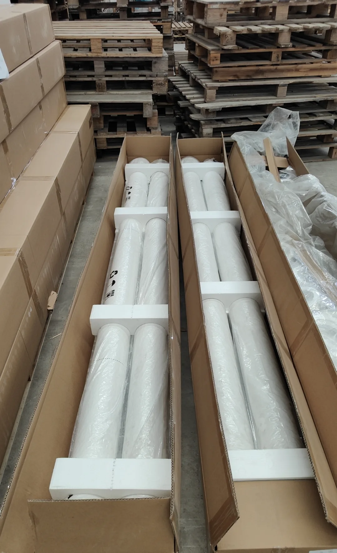
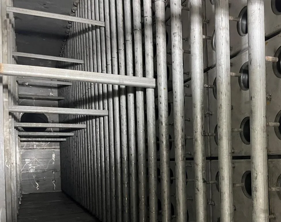
The element is φ150 × φ110 × 3,000 mm with a 20 mm wall and porosity >80%, delivered to OD ±2 mm and length ±20 mm. That tolerance has to be absorbed by the hold-down, not by force during installation. Check tubesheet flatness, hole pattern and pitch against the candle diameter, and confirm you have enough pitch for the pulse jet to reach the bottom of every element. Confirm thermal growth of the tubesheet at peak temperature is free to move, and that the seal design keeps the clean and dirty sides separated while still allowing one person to swap an element from the top.
Pulse-jet and compressed air
Ceramic elements need a short, hard pulse: 0.4–0.7 MPa of dry, oil-free compressed air delivered in 0.1–0.15 s and triggered by differential pressure rather than a timer. That usually means a new manifold and faster valves, because bag timers were built for longer, softer pulses. Size the air receiver so one complete cleaning cycle can run without the header pressure dropping below 0.4 MPa, and put a differential pressure transmitter with a logged trend on the clean side — it is the primary diagnostic for the rest of the element life.
Step 5 — Commissioning and handover
Commissioning checklist
Sequence the commissioning so that every stage has an acceptance criterion in writing. The point of the table below is not paperwork; it is that each line is a failure mode you would otherwise discover during the first production month.
| Stage | Action | Acceptance criterion |
|---|---|---|
| 1. Dry fit | Trial-install one element per row; check seat and removal path | Element seats without forcing; one person can remove it |
| 2. Leak check | Inspect every seal and gasket before closing the vessel | No visible gap; gasket compression even around the circumference |
| 3. Heat-up | Ramp at the agreed rate; soak before introducing dust | Shell and tubesheet growth absorbed; no thermal shock event |
| 4. Baseline dP | Log clean resistance at the design face velocity | Baseline consistent with 300 Pa at 1 m/min face velocity (clean) |
| 5. Pulse tuning | Set pulse pressure and duration; switch to dP trigger | 0.4–0.7 MPa, 0.1–0.15 s; cleaning starts on differential pressure |
| 6. Load run | Introduce full gas flow and dust loading; trend for 72 hours | System resistance stable inside 900–1,500 Pa |
| 7. Emission test | Sample the stack after a cleaning cycle, not only between cycles | >99.9% dust collection; catalytic duty checked against the 170–300°C window |
| 8. Regeneration plan | Write the ABS regeneration step into the maintenance schedule | 350°C for 12 hours at the agreed interval |
Warranty, spares and monitoring
Service life is more than 5 years, backed by a 5-year written warranty, so register the warranty and record the commissioning baseline dP with it — that baseline is what any future claim is measured against. Hold a small stock of spare elements so a single damaged candle does not become an outage, and keep the differential pressure trend on the historian. Review it monthly: a rising floor after regeneration means chemistry or moisture, a step change means a broken element, and a falling trend with rising emissions means a seal.
What a completed retrofit looks like
On the Shandong 2,500 t/d cement clinker line, retrofitted in 2019, the existing housing was kept and the fabric section was replaced with ceramic candles: new tubesheet adapters, a faster pulse manifold and an insulated casing. The result the operator cared about was not the emission number, it was that the pre-cooling stage and its fan power disappeared and the changeout interval moved from a yearly shutdown item to a planned one. Anchor Filter has since supported 40+ projects on the same engineering pattern, and the installed application references show which duties suit it and which do not.
Frequently asked questions
Can I reuse the existing tubesheet?
Usually yes, with adapters. The element is φ150 mm outside diameter with a ±2 mm tolerance and 3,000 mm long with a ±20 mm tolerance, so what matters is pitch, flatness and whether the hold-down can absorb the length variation. If the sheet is corroded or out of flatness by more than a few millimetres across a row, replace it — sealing is the single most common source of retrofit complaints.
How much downtime does a baghouse retrofit ceramic filter project need?
For a single compartment with the adapters pre-fabricated, plan the mechanical swap in days rather than weeks; the critical path is usually tubesheet modification and casing insulation, not element installation. Vessels converted compartment by compartment can often stay partly online. The schedule risk sits in the survey: an unexpected tubesheet repair or a fan upgrade found during the shutdown is what turns a short stop into a long one.
Do I need a new ID fan?
Not automatically. Build the budget first: 300 Pa at 1 m/min face velocity (clean) for the element and 900–1,500 Pa for the complete system, then compare it with the fan curve at the new gas volume. Retrofits frequently reduce volume because the dilution air that protected the bags is no longer needed, which can leave you with margin you did not have before. Confirm it on paper before the shutdown.
Can catalytic DeNOx be added later?
Only if the gas path already works in the 170–300°C window with the optimum at 220–260°C. Elements can be swapped from non-catalytic to catalytic at a later changeout, but the temperature window, the SO₂ limit of 35 mg/m³ below 280°C and the moisture limit of 20% have to be part of the original design brief. Decide the intent at the retrofit stage even if you buy non-catalytic elements now.
What spare element stock should I hold?
Enough to replace a full row plus a small buffer, typically a low single-digit percentage of the installed count. Ceramic elements are individually replaceable, so spares are insurance against mechanical damage during maintenance rather than against wear-out. With a 5-year written warranty and a service life of more than 5 years, the larger risk is damage during handling, so also specify how elements are packed, stored and lifted.
Do I need to replace the filter housing in a baghouse retrofit?
In most retrofits the existing housing is kept. The mechanical work is a new tubesheet or tubesheet adapters, hold-down hardware, a faster pulse manifold and casing insulation — not a new vessel. Housing replacement is only justified when the shell is corroded through or its geometry cannot accommodate the element length. We supply the ceramic filter elements and adapter hardware; the vessel itself usually stays in service.
If you are planning a baghouse retrofit ceramic filter project, send the vessel drawing, gas analysis and fan curve and we will return a compartment-by-compartment scope with an element count and pressure-drop budget — start the retrofit review.
 English
  Deutsch
  简体中文
简体中文  한국어
한국어  日本語
日本語  Español
  Français
  Italiano
  Türkçe
  Tiếng Việt
  Português
  हिन्दी
  العربية
  Polski
  繁體中文
繁體中文