
Ceramic filter installation is where most of the service life of a rigid filter tube is either won or lost. The element itself is a robust piece of engineering — a sintered ceramic fibre body with a 20 mm wall and more than 80% porosity, rated for continuous 600°C duty and peaks up to 1000°C — but it is brittle in bending and unforgiving of misalignment. A tube seated on a damaged gasket, clamped a couple of millimetres off vertical, or held against a metal restraint of the wrong alloy will usually fail long before its neighbours, and it takes the compartment differential pressure and the emission guarantee down with it. This guide sets out the mechanical installation sequence we specify on site, followed by the fluorescent powder leak detection procedure that proves the vessel is gas-tight before handover.
Why installation accuracy decides filter tube life
A flexible filter bag tolerates a surprising amount of abuse. It can be pulled over a slightly out-of-round cage, it flexes with every pulse, and it stretches over a millimetre of misalignment without complaint. A rigid ceramic tube does none of that. It is a stiff, brittle body that transfers every installation error straight into stress at the sealing face and at the point where the clamp grips it.
Three failure modes dominate the field data, and all three trace back to installation rather than to the material:
- Point loading. A clamp that bears on one side of the tube, or a support ring with a burr on its edge, concentrates load on a small area of ceramic. The tube survives the start-up, then cracks during the first thermal cycle.
- Bypass at the seat. A gasket that is torn, carbonised or compressed unevenly lets raw gas straight through to the clean side. Differential pressure barely moves, which is exactly why the plant does not notice until the stack test.
- Erosion between tubes. Two tubes installed touching each other will abrade where they rub. The dust cake no longer forms on the worn patch and the tube loses local filtration.
None of these show up in the first week. They appear between month six and month eighteen, by which point the compartment has to be opened, the failed tubes pulled, and the whole sequence repeated. Getting the installation right the first time is the cheapest five years of operation you will ever buy.
Matching the metal hardware to the gas temperature
Metal fittings — clamps, support rings, blow pipes and tube sheet adapters — have to be selected for the temperature they actually see, not for the temperature at the furnace outlet. A clamp sitting in the clean gas plenum of a tail-end vessel lives in a very different environment from a clamp in a 900°C kiln filter, and specifiers routinely get this wrong by copying one bill of materials across two plants. The same applies to the ceramic filter elements themselves: match the grade to the duty, not to the last project.
All metal parts should be laser cut and deburred before they reach the vessel. A burr left on a clamp edge is not cosmetic; it becomes a point load on the ceramic surface and a crack initiation site once the plant starts cycling.
| Duty band | Gas temperature at the tube sheet | Typical hardware material | Limiting factor |
|---|---|---|---|
| Low-temperature tail-end | 170–300°C | 316L stainless; carbon steel only where the metal stays above the acid dew point | Corrosion below the dew point, not heat |
| Mid-temperature | 300–600°C | 304 or 316 stainless | Loss of strength and oxidation |
| High-temperature | Above 600°C | 310S heat-resistant stainless or a nickel-based alloy | Creep and scaling; allow for thermal expansion |
| Every band | Any | Laser cut, deburred, no sharp edges | A burr is a point load on ceramic |
Where the design temperature is uncertain, specify one band higher and allow clearance for growth. A clamp that is correctly alloyed but has no room to expand will load the tube just as effectively as one made from the wrong steel.
Ceramic filter installation: the step-by-step sequence
The sequence below assumes a top-access vessel with tubes hung from the tube sheet and cleaned by pulse jet from above. Bottom-access and horizontal arrangements follow the same logic with the lifting step reversed.
- Survey the tube sheet. Check hole diameter against the tube outside diameter, confirm flatness, and grind off weld slag. A tube sheet distorted by heat will not seat a rigid tube, and no amount of clamp torque will fix that.
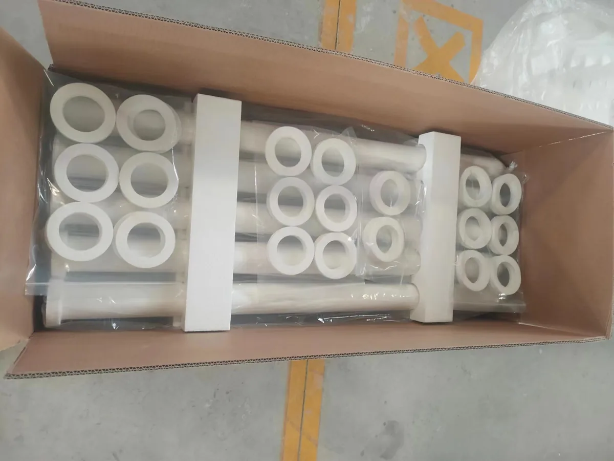
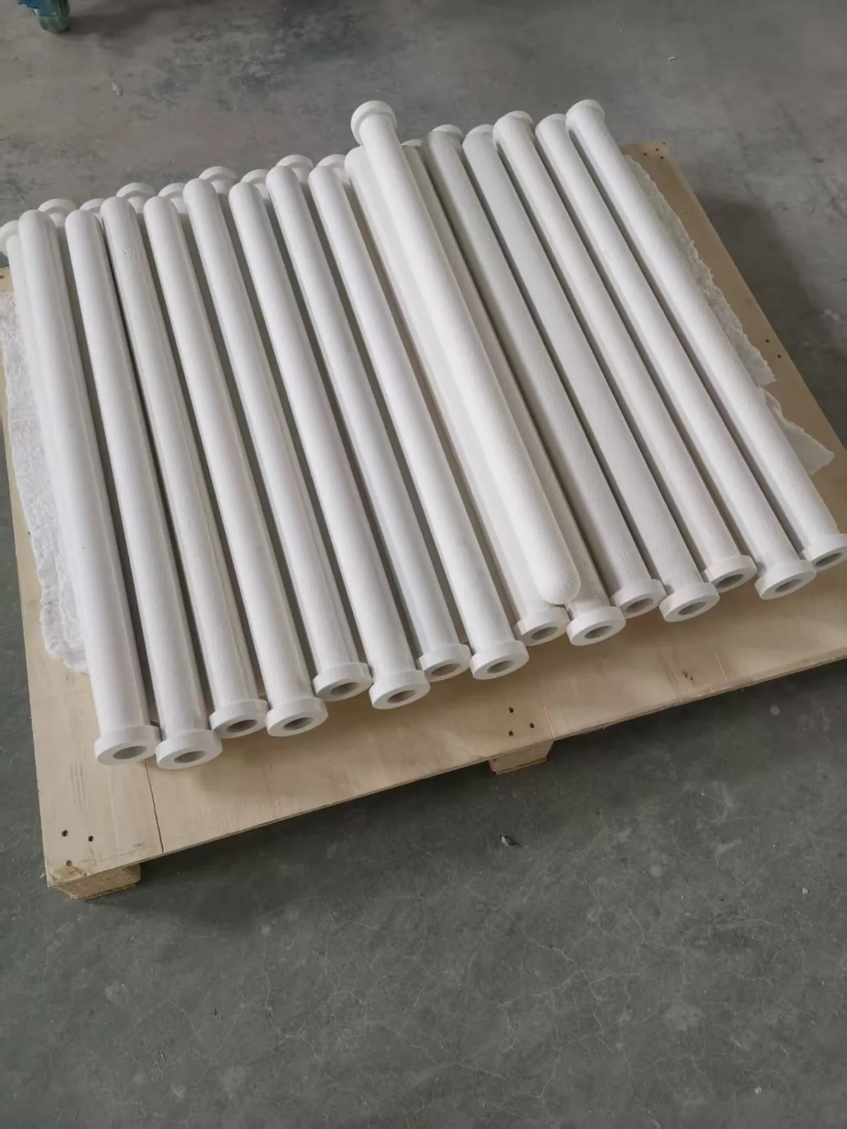
- Verify tube dimensions before lifting. The standard element is φ150 × φ110 × 3,000 mm with a 20 mm wall, held to OD ±2 mm and length ±20 mm. Reject anything with chipped ends, edge cracks or a damaged sealing face.
- Inspect the ceramic aluminium silicate fibre gasket. This is the single most common cause of a failed leak test. Replace it if it is torn, carbonised or has lost resilience.
- Prepare the hardware. Laser-cut clamps and supports, deburr every edge, and confirm the alloy matches the duty band in the table above.
- Seat the tube from the clean side. Lower it vertically into the throat with the gasket in place. Do not drive it with a hammer and do not lever it against the tube sheet — ceramic has no yield point, so it will not deform, it will crack.
- Align the tube. It should hang freely and vertically with the sealing face level and no pre-load from the clamp. Check the gap between neighbouring tubes; they must not touch at any point along their length.
- Fit the clamp evenly. Tighten in a cross pattern to the specified torque so the gasket compresses uniformly around the full circumference rather than heavily on one side.
- Install the blow pipe. Check nozzle concentricity over every tube mouth before the compartment is closed.
- Clear the compartment. Remove tools, packing debris and ceramic dust from the hopper, then close and seal the inspection doors.
Post-installation checks: gaskets, seals and clearances
Before the vessel is closed, run the same checklist on every tube. It takes an hour and it prevents a re-opening that costs a shutdown.
- Gasket condition. Check the ceramic aluminium silicate fibre gasket on every tube. Replace it where it is damaged, carbonised, or no longer springs back when compressed.
- Clamp torque. Uniform around the circumference, to the specified value, not “tight”.
- Blow pipe alignment. Nozzle centred on each tube mouth, pipe supported so it cannot sag.
- Inter-tube clearance. No contact between tubes, and room for thermal growth at the top of the operating range.
- Hopper and doors. Clear of debris, door gaskets seated, no unsealed penetrations.
The gasket check deserves more attention than it usually receives. A ceramic aluminium silicate fibre gasket that has been in a hot, acidic gas stream for a campaign loses resilience long before it looks obviously damaged. If it does not spring back when you press it, it will not seal, and no amount of torque will compensate.
Fluorescent powder leak detection: the procedure
Leak detection is the last step before handover, and it is the only one that gives you direct visual evidence rather than an inference from pressure readings. A fluorescent tracer makes the leak path visible under UV light, which means a small seat leak gets found on day one instead of at the next stack test.
Two conditions are not negotiable. The induced draught fan must run at design air volume, and the pulse-jet cleaning system must be stopped for the duration of the test. Running the fan below design volume will not draw the tracer through every leak path; running the cleaning system will strip the tracer off the tubes before you can look at it.
The dose is weighed in advance: 5–10 g of fluorescent powder per square metre of filtration area. Under-dosing produces a faint, ambiguous trace; over-dosing produces a haze that makes everything glow and tells you nothing.
- Confirm the induced draught fan is at design air volume and the pulse-jet cleaning system is isolated.
- Weigh the tracer at 5–10 g per square metre of filtration area.
- Feed the powder at an opening in the inlet duct, or at the lower inspection port where the vessel has one.
- Let it circulate for several minutes so every tube in the compartment is exposed.
- Stop the fan and wait for the powder to settle.
- Enter the clean side with a UV lamp and scan every tube mouth, gasket line, weld and flange.
- Mark every trace, repair the cause, and repeat the test until the compartment is clean.
| Test parameter | Specified value |
|---|---|
| Fan operation | Induced draught fan at design air volume |
| Cleaning system | Pulse-jet system stopped for the duration of the test |
| Tracer dose | 5–10 g per square metre of filtration area |
| Injection point | Opening in the inlet duct, or the lower inspection port |
| Inspection method | Clean side, UV lamp, after the fan stops and the powder settles |
| Acceptance criterion | No continuous fluorescent trace at any tube mouth, seal or weld |
Sequence matters more than dose. If the cleaning system runs during the test, powder that has landed on a tube is immediately blown back into the gas stream and the trace never forms where you need to see it.
Reading the traces
A continuous trace at a tube mouth almost always means a gasket problem: wrong gasket, damaged gasket, or uneven clamp compression. Pull the tube, replace the gasket and re-seat it rather than simply tightening the clamp further, because over-torque on a rigid tube transfers stress into the ceramic.
A trace along a weld seam or a door flange points to fabrication or assembly rather than to the filter itself. These are usually repaired by welding or by replacing the door gasket, and they should be recorded, because a repeated trace at the same seam means movement in the casing under thermal load.
A faint trace spread evenly across many tubes is usually not a leak at all. It is a dosing artefact — too much powder, too short a settling time, or residual powder in the ductwork from a previous test. Repeat the test with a fresh, correctly weighed dose before you start pulling tubes.
Blow pipe configuration: how many tubes per pipe
Compressed air distribution has a hard limit, and it is worth settling at the design stage because it fixes the compartment layout. Each blow pipe generally covers 18–20 small-diameter filter tubes, or 8–10 large-diameter filter tubes. Exceeding those numbers drops the pulse pressure at the far end of the manifold and the last tubes in the row never clean properly.
| Tube class | Tubes per blow pipe | Note |
|---|---|---|
| Small-diameter ceramic tubes | 18–20 | Most common arrangement; check receiver volume against pulse count |
| Large-diameter ceramic tubes | 8–10 | Higher air volume per pulse; larger compressor margin needed |
| Mixed diameters | Per engineering calculation | Do not mix diameters on a single blow pipe |
The consequence of getting this wrong shows up as a slow, uneven rise in differential pressure: a few tubes carry a permanent cake while their neighbours stay clean, and the compartment looks under-designed when in fact it is only under-piped.
Why rigid tubes do not flex, and why that suppresses secondary dust
Pulse-jet cleaning on this equipment runs at 0.4–0.7 MPa for 0.1–0.15 s, triggered by differential pressure rather than by a fixed timer. Because the tube is rigid, the pulse does not inflate it. A fabric bag expands under the pulse and snaps back, and that movement throws a fraction of the freshly released dust straight back into the gas stream — secondary dust, which then has to be re-filtered and which shows up as a pressure spike after every cleaning cycle.
A rigid ceramic tube has none of that movement. The pulse releases the dust cake as a sheet, the cake falls into the hopper, and there is no re-entrainment and no secondary dust plume. That behaviour is why the cleaning interval can be set purely on differential pressure, and why the pressure trace after a pulse is flat rather than spiked.
It is also why the tube keeps its shape over a long campaign. There is no fatigue from repeated flexing, which is a significant part of the reason the element is expected to last more than 5 years and is supplied with a 5-year written warranty.
Commissioning values to record at handover
Record the following on the first stable day of operation and keep them as the baseline for the warranty period. These are the figures we publish on our performance data page, and they are the ones every later diagnostic compares against.
| Item | Value |
|---|---|
| Initial pressure drop | 300 Pa at 1 m/min face velocity (clean) |
| System resistance in stable operation | 900–1,500 Pa |
| Filtration velocity | 2–5 cm/s (≈1.2–3.0 m³/min per m²) |
| Pulse-jet cleaning | 0.4–0.7 MPa, 0.1–0.15 s, triggered by differential pressure |
| Filtration efficiency | >99.9% |
| Dioxin removal (catalytic grade) | up to 99.5% (TEQ) |
| Design life | more than 5 years, backed by a 5-year written warranty |
We have been designing, installing and commissioning these systems since 2019 and have delivered 40+ projects, including a 750 t/d municipal waste incineration line in Nansha, Guangzhou, and a 2,500 t/d cement clinker line in Shandong that has been running since 2019. The installation discipline described here is the discipline used on those sites. Where no DeNOx duty is required, the same sequence applies to our non-catalytic ceramic fibre filter tubes.
Frequently asked questions
How long does ceramic filter installation take for one compartment?
For a crew of four working a standard compartment, mechanical installation runs one to two days including gasket replacement and blow pipe alignment. Fluorescent powder leak detection adds roughly half a day including the settling and inspection time. Rushing the leak test is the most expensive shortcut available on the project.
Can the old gasket be reused if it still looks intact?
Only if it has never been in service on a hot, acidic gas stream and still springs back when compressed. In practice, on any re-tube we replace the ceramic aluminium silicate fibre gasket as standard. The gasket costs a fraction of the labour needed to open the vessel a second time.
Why does the pulse-jet cleaning system have to be stopped during leak detection?
Because the tracer needs to stay where it lands. If cleaning runs, the powder that has deposited around a leak path is blown back into the gas stream before the UV inspection, and the leak becomes invisible. Stop the cleaning system, run the fan, dose, stop the fan, settle, then inspect.
What if a leak is only discovered after start-up?
A leak found in service usually shows as an unexplained rise in differential pressure or as dust on the clean side of one compartment. The repair is the same: isolate the compartment, open it, find the failed seat or gasket with a tracer test, and replace the gasket. The difference is that you have lost production time doing it.
How often should leak detection be repeated?
At every re-tube, after any major casing repair, and as part of the annual outage inspection. Plants that run a tracer test at each outage rarely see emission excursions between tests. More detail on inspection frequencies is on our technical Q&A page.
Planning a ceramic filter installation or a leak-detection audit? Send us your vessel drawings and gas analysis and our engineers will come back with a tube count, a blow pipe layout and an installation sequence. Request an installation review.
 English
  Deutsch
  简体中文
简体中文  한국어
한국어  日本語
日本語  Español
  Français
  Italiano
  Türkçe
  Tiếng Việt
  Português
  हिन्दी
  العربية
  Polski
  繁體中文
繁體中文