
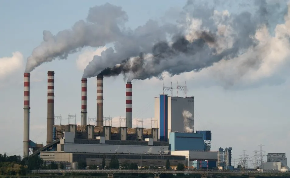
Dioxins are the most tightly regulated pollutants leaving a municipal or hazardous waste incinerator, and the conventional answer — activated carbon injection — destroys nothing. It moves the molecule out of the gas phase and into a spent carbon residue that still has to be landfilled or thermally treated somewhere else. A dioxin removal filter built on selective catalytic oxidation (SCO) takes the opposite route: PCDD/PCDF molecules are oxidised into CO₂, H₂O and HCl as they pass through the catalyst-loaded wall of a ceramic fiber filter element, while that same element is removing dust, acid gas and NOx inside one vessel. Below we cover the chemistry, the 170–300 °C reaction window, the inlet SO₂ limit that decides whether the system works, and the emission levels actually achieved in service.
What “Dioxin” Actually Means: 210 Congeners, One Toxicity Benchmark
Dioxin is not a single compound. It is a family of 210 chlorinated aromatic substances: 75 polychlorinated dibenzo-p-dioxin (PCDD) isomers and 135 polychlorinated dibenzofuran (PCDF) isomers. Only the 17 congeners chlorinated in the 2,3,7,8 positions carry meaningful toxicity, and each is weighted against the most heavily studied of them, 2,3,7,8-tetrachlorodibenzo-p-dioxin (2,3,7,8-TCDD). The International Agency for Research on Cancer classified 2,3,7,8-TCDD as a Group 1 human carcinogen in 1997, which is why permits are written in toxic equivalency (TEQ) rather than total mass.
That distinction is practical, not academic. A stack result reported in ng TEQ/m³ can look stable for months while the underlying congener fingerprint shifts with fuel composition, combustion stability and ash chemistry. A control technology therefore has to attack the entire family across its full chlorination range, not just the marker congener the laboratory happens to report. Waste incineration is consistently identified as one of the dominant sources, responsible for roughly 10%–40% of total dioxin releases to air depending on the country and the age of the installed fleet.
Why Dioxins Are Hard: Destroyed Above 700 °C, Re-Formed on the Way Down
Thermal destruction of PCDD/PCDF needs temperatures above 700 °C combined with sufficient residence time and turbulence — the classic 3T rule. Well-run incinerators meet that in the secondary chamber without difficulty. The problem is everything that happens after it. As the gas cools through roughly 400 °C down to 200 °C on its way to the air pollution control train, dioxins re-form by de novo synthesis on the surface of fly ash particles, using the chlorine, residual carbon and copper already present in that ash as raw material and catalyst.
This re-synthesised fraction is the hardest part of the problem, and it is the reason “we burn at 850 °C” is not an acceptable answer during permitting. The molecules measured at the stack were largely created after the flame, on particle surfaces, inside the cooling duct — precisely the temperature band where conventional control equipment sits. Any serious dioxin removal filter must therefore be positioned in that cooling zone and handle formation and destruction simultaneously, at low temperature, in a heavily dust-laden stream.
How Selective Catalytic Oxidation Works Inside the Filter Wall
Selective catalytic oxidation is an oxidative process, not a reductive one. No ammonia and no additional reagent are consumed for the dioxin reaction itself: the oxygen already present in the flue gas is the oxidant. Inside a defined reaction temperature band, the catalyst dispersed through the wall thickness of the ceramic fiber element contacts the PCDD/PCDF molecule as it diffuses through the porous structure, breaks the aromatic ring and strips the chlorine, leaving CO₂, H₂O and HCl as the end products. The HCl is then captured downstream, or in the alkaline filter cake, exactly like any other acid gas.
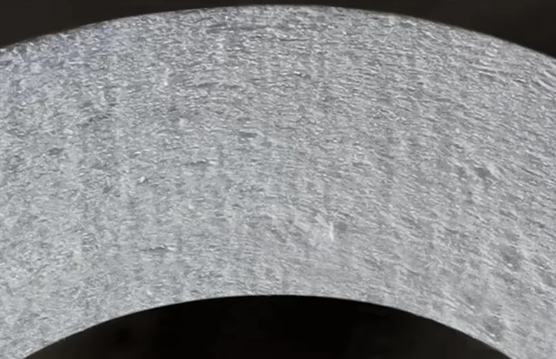
The geometry matters here. Because the catalyst is distributed through the full 20 mm wall rather than painted onto a surface, the gas cannot bypass it: every cubic metre that leaves the vessel has passed through a catalytically active depth of material with a residence time far longer than a honeycomb channel can offer at the same face velocity. The ceramic fiber substrate also carries the same function it always has — a rigid, high-temperature filter medium with porosity above 80%, which is what allows one element to do filtration and catalysis at the same time. You can read more about the construction on our catalytic ceramic fiber filter page.
Reaction Window: 170–300 °C, Optimum 220–260 °C
Temperature is the single most important design variable, because the same catalyst bed is being asked to destroy dioxins and reduce NOx at the same time. Below about 170 °C the oxidation kinetics slow down and the vessel drifts into the region where ammonium bisulfate can condense if ammonia is being injected for DeNOx. Above 300 °C the DeNOx reaction no longer improves measurably, the SO₂-to-SO₃ conversion rate climbs, and long-term thermal ageing of the catalyst accelerates.
| Flue gas temperature | DeNOx efficiency | Dioxin destruction | Engineering note |
|---|---|---|---|
| 170 °C (lower bound) | Below design point | Active but slower kinetics | Watch for ABS condensation if NH₃ is injected |
| 200 °C | 90% | Above 95% (TEQ) | Typical tail-end position after a waste heat boiler |
| 220–260 °C (optimum) | 94–97% | up to 99.5% (TEQ) | Design target; best balance of destruction and DeNOx |
| 280 °C | 98% | Above 99% (TEQ) | Higher DeNOx, but monitor SO₃ formation |
| 300 °C (upper bound) | 98% | Above 99% (TEQ) | Upper limit; avoid sustained operation above this |
In practical terms this window is a good match for the tail-end of a waste incineration line, downstream of the boiler and upstream of the induced draft fan. It is also the reason the technology is described as low-temperature: no reheating with natural gas or steam is needed to reach the catalytic band, which is the largest single operating cost difference against a conventional high-dust SCR arrangement.
The Inlet SO₂ Limit: Keep It Below 50 mg/m³ (S.T.P., dry)
SO₂ is the one contaminant that will quietly ruin a SCO system if it is left unmanaged. Sulphur dioxide competes for the same active sites the dioxin molecule needs, and at elevated concentrations it occupies enough of them that PCDD/PCDF destruction efficiency drops sharply even though the catalyst is still physically intact. The design boundary is an inlet concentration below 50 mg/m³ (S.T.P., dry) at the reactor inlet.
Where raw SO₂ is higher than 50 mg/m³ (S.T.P., dry), inject alkaline dry powder ahead of the reactor for dry desulphurisation. The sorbent consumes SO₂ before the gas reaches the catalytic wall, and the resulting reaction products are captured on the filter surface as part of the dust cake. This is a standard dry scrubber arrangement, not a wet system — no wastewater stream, no reheating penalty.
There is a second benefit to that upstream sorbent. Because the alkaline powder also neutralises HCl and HF, it protects the catalyst from the chemical boundaries every ceramic system has to respect — fluoride above 5 ppm, phosphoric acid mist, and alkali oxides (Na₂O, K₂O) in the absence of an alkaline absorbent. Plants that skip the dry sorbent step to save reagent cost typically pay for it later in catalyst life.
Two-Stage Capture: Dust Cake Interception Plus In-Wall Cracking
Dioxin removal in this system happens in two places, and understanding both helps explain why measured efficiency is so high. First, particulate matter is intercepted on the outer surface of the element, where filtration efficiency exceeds 99.9%. A significant share of the dioxin mass in an incinerator flue gas is adsorbed onto the surface of fly ash particles, so those molecules never reach the catalyst at all — they are removed with the dust cake and discharged with the ash.
Second, the vapour-phase fraction that does pass through the dust cake and into the wall is cracked by the catalyst on its way to the clean side. Anything that escapes both stages would have to be a molecule that neither adsorbed onto a particle nor contacted an active site during a residence time of several seconds inside a 20 mm porous wall, which is a very unlikely path. This two-stage mechanism is also why performance stays stable across load swings: the dust cake thickens slightly at higher dust loading and does the extra work.
Integrated Emission Performance in One Vessel
Because the same filter element carries the catalytic function, a single vessel can be specified against four pollutants simultaneously rather than four separate guarantees from four vendors.
| Pollutant | Outlet level | Mechanism |
|---|---|---|
| Particulate | ≤5 mg/m³ | Surface filtration, >99.9% efficiency |
| SO₂ | ≤30 mg/m³ | Dry alkaline sorbent plus reactive filter cake |
| NOx | ≤50 mg/m³ | NH₃-SCR on catalyst in the filter wall |
| Dioxins (PCDD/PCDF) | up to 99.5% removal (TEQ) | Selective catalytic oxidation at 170–300 °C |
The full test data behind these figures, including pressure drop development over time, is summarised on our performance page.
Activated Carbon Injection vs. Catalytic Destruction
Activated carbon injection is the incumbent technology and it does reduce measured stack concentrations, so it deserves a fair description. Its limitation is not removal efficiency — it is what happens to the pollutant afterwards. Adsorption concentrates PCDD/PCDF onto the carbon, which is then collected in the baghouse together with the fly ash. The dioxin has not been destroyed; it has been transferred into a solid residue that in most jurisdictions is classified as hazardous and must be landfilled or fed back into the kiln or furnace.
| Criterion | Activated carbon injection | SCO catalytic ceramic filter |
|---|---|---|
| Fate of the pollutant | Transferred to spent carbon and fly ash | Destroyed to CO₂, H₂O and HCl |
| Residue classification | Dioxin-bearing hazardous ash | Ash free of added dioxin load |
| Consumable | Continuous powdered carbon dosing | No carbon; alkaline sorbent only if SO₂ requires it |
| Additional functions | Dioxin only | Dust, SO₂, NOx and dioxin in one vessel |
| Sensitivity | Carbon quality, dosing rate, mixing | Temperature window and inlet SO₂ |
For an operator whose ash disposal cost is rising or whose permit is being tightened, that difference is usually decisive. Carbon injection solves the stack measurement; catalytic oxidation solves the material balance.
Element Specification and Operating Envelope
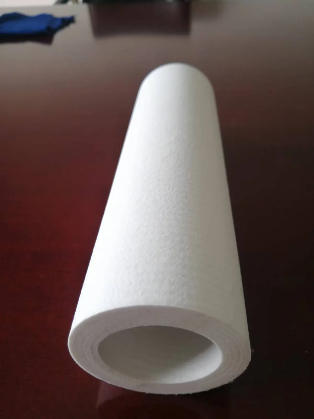
The element is a rigid ceramic fiber candle with catalyst integrated through the wall. Standard geometry and operating limits are listed below; these are the numbers your fan, vessel and cleaning system have to be sized against.
| Parameter | Value |
|---|---|
| Dimensions | φ150 × φ110 × 3,000 mm |
| Wall thickness | 20 mm |
| Dimensional tolerance | OD ±2 mm / length ±20 mm |
| Porosity | >80% |
| Clean differential pressure | 300 Pa at 1 m/min face velocity (clean) |
| Operating system resistance | 900–1,500 Pa |
| Filtration velocity | 2–5 cm/s (≈1.2–3.0 m³/min per m²) |
| Pulse-jet cleaning | 0.4–0.7 MPa, 0.1–0.15 s, differential-pressure triggered |
| Continuous service temperature | 1100 °C |
| Short-term peak | 1300 °C for no more than 30 min |
| Service life | more than 5 years, with a 5-year written warranty |
Where This Configuration Is Already Running
Anchor was founded in 2019 and has since delivered more than 40 projects across incineration, cement, glass, steel and non-ferrous applications. The reference most relevant to dioxin control is a 750 t/d municipal waste incineration line in Nansha, Guangzhou, where catalytic filter elements handle dust, acid gas, NOx and dioxin in a single vessel at the tail end of the line. A second long-running reference is a 2,500 t/d cement clinker line in Shandong, commissioned in 2019, which demonstrates the mechanical durability of the element in a high-dust, high-alkali environment over multiple campaigns.
Further sector-by-sector arrangements, including where SCO sits relative to the boiler and the dry scrubber, are described on our applications page.
Frequently Asked Questions
What temperature does a dioxin removal filter need to operate at?
Between 170 °C and 300 °C, with the best combined dioxin and NOx performance at 220–260 °C. At 200 °C the DeNOx efficiency is around 90%; at 280 °C it reaches 98%. Dioxin destruction remains above 95% (TEQ) across the whole band and peaks at up to 99.5% (TEQ) in the optimum range, so no reheating of the flue gas is normally required.
Why does inlet SO₂ have to stay below 50 mg/m³?
Because SO₂ competes for the same catalytic active sites that PCDD/PCDF molecules need. Once a significant share of those sites is occupied by sulphur species, dioxin destruction efficiency falls even though the catalyst is undamaged. Where the raw gas exceeds 50 mg/m³ (S.T.P., dry), dry alkaline powder is injected ahead of the reactor to bring SO₂ down before the gas reaches the catalytic wall.
Is activated carbon still needed alongside a catalytic filter?
In most designs, no. Activated carbon injection transfers dioxin from the gas phase onto a solid that then has to be disposed of, whereas SCO decomposes it to CO₂, H₂O and HCl. Removing carbon dosing also removes a consumable cost and avoids loading the fly ash with additional dioxin mass. Some plants still keep carbon injection as a standby for upset conditions.
How long do the catalytic filter elements last?
Service life is more than 5 years under normal operating conditions, backed by a 5-year written warranty. Actual life depends mainly on three things: staying inside the 170–300 °C window, keeping inlet SO₂ below the design limit, and respecting the chemical boundaries for fluoride, phosphoric acid mist and alkali oxides.
Can an existing baghouse be converted to catalytic dioxin control?
Frequently yes. The vessel geometry, tube sheet and pulse-jet cleaning system of a baghouse are usually compatible with ceramic candles of φ150 × φ110 × 3,000 mm, so the conversion is mostly a matter of element count, cage and header adaptation. The checks that matter are available fan margin against 900–1,500 Pa operating resistance and whether the existing gas temperature sits inside the catalytic window.
Which chemicals damage the catalyst?
Hydrogen fluoride above 5 ppm, phosphoric acid mist, and alkali oxides (Na₂O, K₂O) in the absence of an alkaline absorbent. Running alkaline dry sorbent ahead of the reactor neutralises most of these before they reach the wall, which is why the dry desulphurisation step is recommended even on fuels with modest sulphur content.
Send us your flue gas volume, temperature profile, SO₂ and dust loading and we will size a catalytic filter vessel against your dioxin permit limit, with expected pressure drop and element count. Request an engineering proposal.
 English
  Deutsch
  简体中文
简体中文  한국어
한국어  日本語
日本語  Español
  Français
  Italiano
  Türkçe
  Tiếng Việt
  Português
  हिन्दी
  العربية
  Polski
  繁體中文
繁體中文