
Anyone who has specified a ceramic filter vs bag filter for the same vessel eventually stops asking which media filters better and starts asking which one fails in a way the plant can absorb. Bag media fails by melting, blinding or tearing, usually without warning and usually halfway through a campaign you cannot stop. Ceramic candle elements fail slowly, through creep in differential pressure, and they give you months of warning. The twelve differences below are the ones that actually move project economics once your gas stream climbs past the fabric limit.
Temperature, efficiency and velocity
1. Continuous temperature ceiling: 600°C (1000°C peak) against roughly 260°C
Bag media is a polymer or a coated glass fibre. PPS, P84, PTFE and aramid felts work between roughly 160°C and 260°C; a woven fibreglass fabric with a high-temperature finish reaches about 280°C, and only for short periods. Above that, the only way to keep bags alive is to cool the gas with dilution air, a heat exchanger or a water quench, each of which adds volume, fan power and condensation risk. Ceramic fibre candles run continuously at 600°C and tolerate peaks up to 1000°C, so a furnace upset that would destroy a baghouse in seconds becomes an event the ceramic vessel rides through and logs.
2. Filtration efficiency at the stack
Ceramic elements hold >99.9% collection efficiency because the filter body itself is the barrier, not a dust cake that forms and is then blown off. A baghouse depends on that cake, so its efficiency is excellent between cleaning pulses and weakest immediately after one. If your permit is written on an hourly average, the difference is invisible. If it is written on a peak, or if the stack test happens to overlap a cleaning cycle, it is the difference between a pass and a deviation report. The filtration principle behind a rigid ceramic body is worth reading before you write the guarantee into a contract.
3. Filtration velocity and vessel size
Ceramic candles in hot duty are designed at 2–5 cm/s (≈1.2–3.0 m³/min per m²). Baghouses are commonly engineered around 0.8–1.5 m/min of air-to-cloth, which is the same order of magnitude, so a switch rarely buys you capacity from velocity alone. What it buys is the removal of the cooling duty ahead of the filter, and with it the extra gas volume you were paying to move, to treat and then to reheat.
Pressure drop, cleaning and service life
4. Pressure drop: baseline and drift
A clean element measures 300 Pa at 1 m/min face velocity (clean). A complete system, including the dust layer, tubesheet, hopper and ducting, settles between 900 and 1,500 Pa, with 900–1,300 Pa typical in glass furnace duty. Baghouse resistance is dominated by the cake and moves like a sawtooth on a rising floor. The ceramic trace is flatter, and its floor drifts over months rather than shifting between shifts, which is why differential pressure becomes a usable condition indicator instead of a nuisance alarm. The curves behind those numbers are published on our measured performance data page.
5. Pulse-jet cleaning
Ceramic elements are rigid, so cleaning is a short, hard shock: 0.4–0.7 MPa of compressed air delivered in a 0.1–0.15 s pulse, triggered by differential pressure rather than by a timer. Bags need a gentler, longer pulse to flex the fabric without abrading it, and they are usually cleaned on a fixed cycle whether or not they need it. Pressure-triggered cleaning also cuts compressed air consumption, which on a large vessel is a measurable operating line.
6. Service life and warranty
Service life is more than 5 years, backed by a 5-year written warranty. Bag media in the same hot, acidic service is typically replaced every one to three years, and every changeout carries scaffold, confined-space entry, disposal of dust-laden media and a production stop. Multiply that by the number of campaigns in a decade and the media price difference stops being the deciding variable.
Ceramic filter vs bag filter: the numbers side by side
| Parameter | Ceramic candle filter | Bag filter (typical hot duty) |
|---|---|---|
| Continuous gas temperature | 600°C continuous; 1000°C peak | About 160°C to 260°C; up to ~280°C with treated fibreglass |
| Clean pressure drop | 300 Pa at 1 m/min face velocity (clean) | Cake-dependent; no stable clean baseline |
| Total system resistance | 900–1,500 Pa (900–1,300 Pa in glass furnace duty) | Commonly designed around 1,000–1,500 Pa with cake included |
| Collection efficiency | >99.9% independent of cleaning cycle | 99.5–99.9% once the cake is established; dips after each pulse |
| Filtration velocity | 2–5 cm/s (≈1.2–3.0 m³/min per m²) | Commonly 0.8–1.5 m/min air-to-cloth |
| Pulse cleaning | 0.4–0.7 MPa, 0.1–0.15 s, differential-pressure triggered | Lower pressure, longer pulse, usually timer-driven |
| Service life | more than 5 years with a 5-year written warranty | One to three years in hot, acidic service |
| Catalytic function | DeNOx and dioxin destruction inside the same element | Not available |
| Moisture limit | Below 20% by volume; ABS removed by 350°C × 12 h regeneration | Blinding and hydrolysis risk near the dew point |
Read the table as a decision tool rather than a scorecard. If your stream sits above the fabric temperature limit, or if the permit requires gas-phase destruction of NOx or dioxins, the comparison is settled before you reach row nine. If your stream is cool, dry, chemically mild and comfortably inside fabric limits, a baghouse remains the lower-cost answer, and no honest supplier should tell you otherwise. The interesting cases are the middle ones, where temperature spikes are short, chemistry is marginal, or a catalytic function would remove a vessel from the flowsheet — and those are the cases worth engineering rather than quoting.
Chemistry, moisture and catalytic function
7. Acid and alkali boundaries
Ceramic fibre is not inert to everything, and this is where most specification mistakes are made. Sustained HF above 5 ppm attacks the fibre bond. Phosphoric acid (H₃PO₄) mist is excluded outright. Free Na₂O or K₂O alkali will flux the surface at temperature unless an alkaline sorbent is being injected upstream. Where a catalytic section runs below 280°C, SO₂ has to stay under 35 mg/m³. These are boundaries, not preferences: crossing them is what turns a warranty claim into an argument.
- ■ HF: keep sustained exposure below 5 ppm.
- ■ H₃PO₄ mist: excluded from the duty entirely.
- ■ Na₂O / K₂O: only acceptable with an alkaline sorbent dosed upstream.
- ■ SO₂ below 280°C: hold under 35 mg/m³.
8. Moisture, dew point and ammonium bisulphite
Keep moisture below 20% by volume. Beneath the dew point, capillary condensation inside the pore structure raises differential pressure quickly and the element looks blinded when it is simply wet. Where ammonia slip is present, ammonium bisulphite (ABS) deposits accumulate in the same temperature band. The remedy is scheduled rather than emergency: periodic regeneration at 350°C for 12 hours decomposes the deposit and returns the element to its baseline resistance.
9. Catalytic DeNOx and dioxin destruction in the same element
A catalytic ceramic element does something no bag can do: it destroys NOx and dioxins while it filters dust. The catalyst works across a 170–300°C window with the optimum at 220–260°C. With the low-temperature catalyst formulation, expect about 90% DeNOx at 200°C and about 98% at 280°C, while dioxin destruction reaches up to 99.5% (TEQ) by selective catalytic oxidation. In practice that collapses an SCR vessel, its casing and its reheat into the filter housing — provided your stream genuinely sits inside the window. See the catalytic ceramic fibre filter elements for the full window definition.
Geometry, failure modes and cost
10. Element geometry and how it constrains the vessel
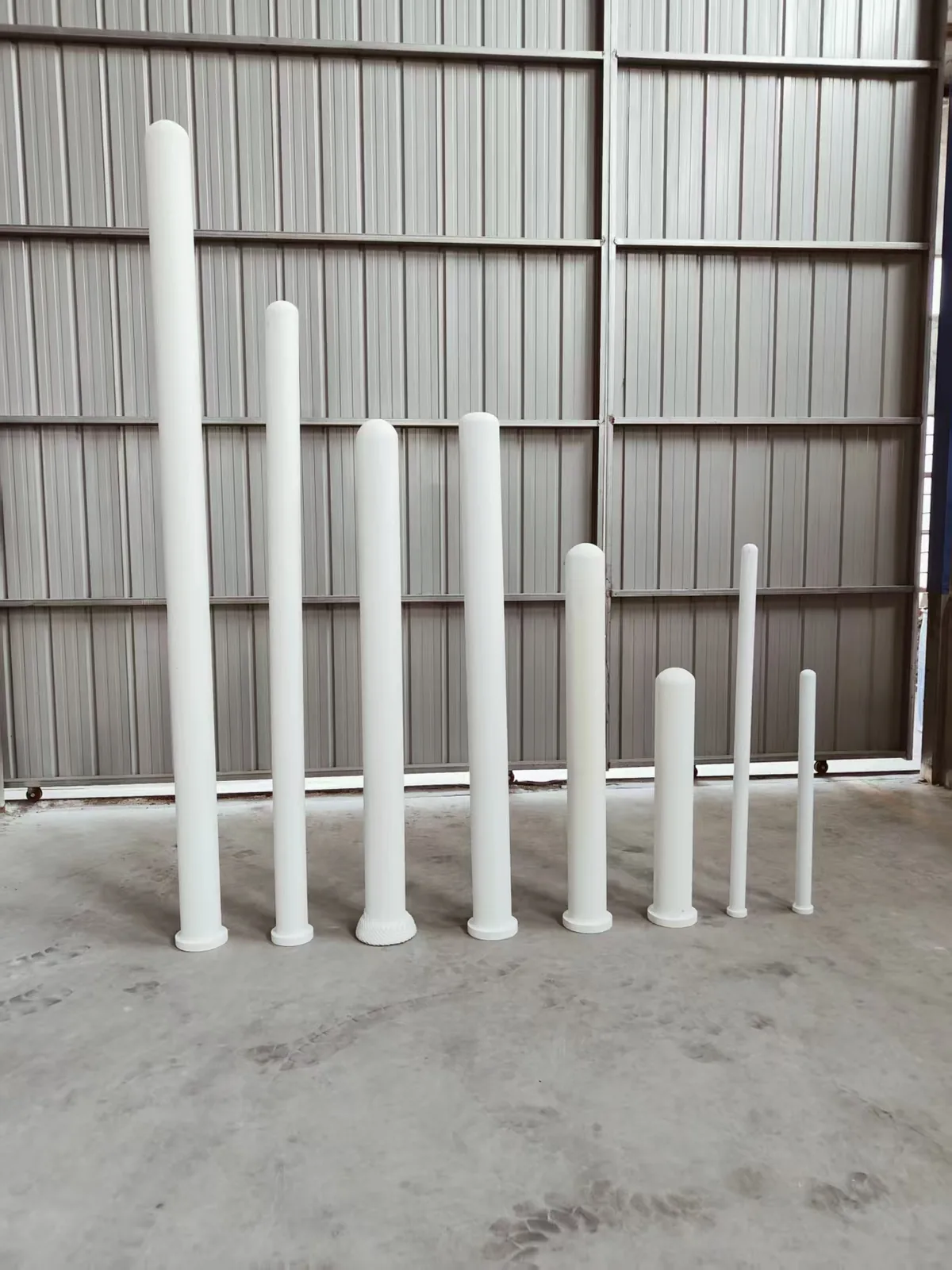
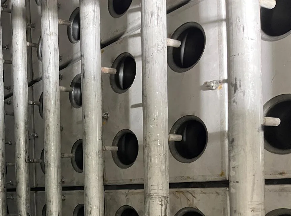
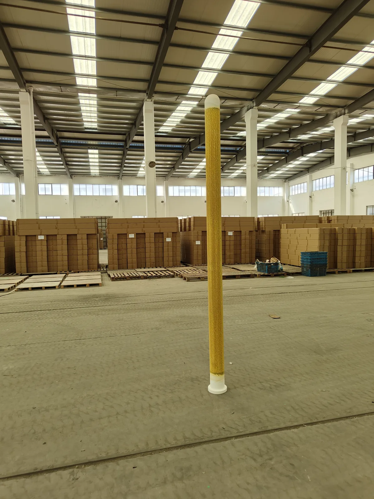
The standard candle is φ150 × φ110 × 3,000 mm with a 20 mm wall and porosity >80%. Manufacturing tolerance is OD ±2 mm and length ±20 mm, so hold-down hardware has to absorb that variation rather than fight it, and the tubesheet has to be flat enough to seat every element without point loading. Porosity above 80% is what keeps the clean pressure drop at 300 Pa at 1 m/min face velocity (clean) while the element still carries its own weight at 600°C. The non-catalytic ceramic fibre filter elements page lists the full dimension set.
11. Failure modes you can actually monitor
Bags fail catastrophically and locally: one torn sleeve and the opacity monitor tells you within minutes, but it does not tell you which of four hundred sleeves it is. Ceramic elements crack rather than tear, usually from thermal shock during heat-up or from mechanical overload at the seal, and a crack shows up first as a slow rise in differential pressure or as dust trails on the clean side during inspection. Both modes are detectable; only one of them converts into a scheduled repair rather than an unplanned outage.
12. Where the money actually goes
Compare the two options over the life of the vessel, not over one purchase order. The bag column carries media replacement every one to three years, the labour for each changeout, disposal of dust-laden bags, the fan power for dilution air and the reheat downstream of it. The ceramic column carries one element set with a 5-year written warranty, no cooling duty, pressure-triggered cleaning and one planned intervention instead of four. Anchor Filter has been building these elements since 2019 and has delivered 40+ projects; the plants that gained the most were the ones where the gas was already too hot for any fabric.
Frequently asked questions
How hot can the gas enter a ceramic candle filter without pre-cooling?
Up to 600°C continuously, with peaks to 1000°C permitted. That removes the dilution air, heat exchanger or quench that a fabric filter would need above roughly 260°C. Thermal shock, not steady temperature, is what you must control: ramp the vessel at a defined rate during heat-up and never quench a hot element with cold air.
Is the >99.9% efficiency figure independent of the cleaning cycle?
Yes. The ceramic body is the barrier, so collection efficiency does not collapse immediately after a pulse the way a cake-dependent fabric does. That matters when your permit is written on peak rather than hourly average emissions, or when a stack test overlaps a cleaning sequence. It also means the emission guarantee can be written without a caveat about cleaning state.
Which chemical conditions will void the element warranty?
Sustained HF above 5 ppm, any phosphoric acid mist, and free Na₂O or K₂O alkali without an alkaline sorbent dosed upstream. Where a catalytic section operates below 280°C, SO₂ must stay under 35 mg/m³, and moisture should stay below 20% by volume. ABS deposits are manageable if you schedule periodic regeneration at 350°C for 12 hours.
Do ceramic elements remove NOx and dioxins as well as dust?
Only the catalytic grade does. Its window is 170–300°C with the optimum at 220–260°C; the low-temperature formulation delivers roughly 90% DeNOx at 200°C and about 98% at 280°C, and dioxin destruction reaches up to 99.5% (TEQ). A non-catalytic element in the same housing still filters at >99.9% but performs no gas-phase destruction.
What filtration velocity should I design the vessel around?
Design between 2 cm/s and 5 cm/s, which is about 1.2–3.0 m³/min per m² of filter area. Stay at the lower end for fine, sticky or high-loading dust and for catalytic duty, where residence time inside the wall matters as much as surface area. Velocity is also your lever on pressure drop: the clean element figure of 300 Pa is quoted at 1 m/min face velocity (clean).
What is a PTFE membrane filter, and where does it stop?
A PTFE membrane filter is a fabric bag laminated with a micro-porous PTFE surface layer that improves dust release and raises efficiency. The membrane itself is chemically inert, but the bag underneath is still fabric: the continuous temperature limit stays around 250–260°C, set by the base cloth rather than the membrane. Above that, the laminate survives minutes, not campaigns — for continuous duty beyond the fabric limit, a rigid ceramic body is the appropriate media.
Are fiberglass filters safe above 260°C?
Standard fiberglass bag media is rated to about 240–260°C continuous; specially finished fabrics tolerate short excursions near 280°C. Sustained operation above that window burns out the binder and embrittles the fabric, which shows up as rising emissions and torn bags rather than a clean warning. For continuous duty above 260°C, ceramic fiber elements — 600°C continuous, 1000°C peak — are the safer specification.
What is the temperature limit of a HEPA filter?
Standard HEPA elements are limited to roughly 70–90°C; special high-temperature HEPA constructions reach about 350°C in clean-air duty such as ovens and cleanrooms. HEPA is a clean-side air filtration technology, not a flue gas technology: for dust-laden hot gas above 260°C, ceramic fiber filtration (600°C continuous, 1000°C peak) is the appropriate class.
If you are weighing a ceramic filter vs bag filter against a real gas analysis, send us the stream data and the vessel drawing and we will return an element count and pressure-drop estimate for both options — request an engineering comparison.
HEPA, PTFE Membrane and Fiberglass: Common Questions
Is there a high temperature HEPA filter?
Standard HEPA media is fine glass-fiber paper with polymer binders and is not rated for hot gas. So-called high temperature HEPA filters — or, in shorter search terms, a high temp HEPA filter — use special binders and frames, but still sit far below the 600°C continuous rating of ceramic fiber elements. For hot dust-laden gas above 260°C, a ceramic element is the practical equivalent, with filtration efficiency above 99.9%.
What is a PTFE membrane filter?
To answer “what is PTFE membrane filter” in one sentence: it is a fabric bag laminated with a thin PTFE surface layer that improves dust release and filtration efficiency. The membrane and its fabric support both fail above roughly 260°C — beyond that, ceramic candle filters take over, with no textile layer to degrade.
Are fiberglass air filters better, and are fiberglass filters safe?
Fiberglass filter bags resist heat better than polyester, up to roughly 260°C, and are dimensionally stable, but they still cannot match ceramic fiber at 600°C. On safety: intact fiberglass media is safe in service; the practical concern is fiber shedding during change-out, which rigid ceramic elements avoid.
 English
  Deutsch
  简体中文
简体中文  한국어
한국어  日本語
日本語  Español
  Français
  Italiano
  Türkçe
  Tiếng Việt
  Português
  हिन्दी
  العربية
  Polski
  繁體中文
繁體中文