
Working Principle of Ceramic Fiber Filters
Understanding Ceramic Fiber Filtration: 17 Years of Field Experience
We’ve been designing and troubleshooting ceramic fiber filtration systems since 2008, and we’ve learned that successful operation depends on understanding three critical interactions: (1) the gas-particle-ceramic interface during filtration, (2) the dust cake formation and release cycle during pulse-jet cleaning, and (3) the thermal and chemical environment’s long-term effect on the ceramic structure. This page explains the working principle based on actual operating data from our 300+ installations, not just theoretical models from textbooks.
The most common mistake we see in failed ceramic filter installations (often supplied by competitors who don’t understand the technology) is improper pulse-jet cleaning system design. If the compressed air pressure is too low (<0.3 MPa), the dust cake doesn’t release completely and pressure drop climbs uncontrollably. If the pulse interval is too long (>60 seconds), the cake becomes too thick and compresses against the filter surface, making it harder to remove. If the pulse valve is undersized or the air receiver tank is too small, you get pressure droop during the pulse and incomplete cleaning. We specify 0.4–0.7 MPa pulse pressure, 10–30 second intervals (adjusted based on dust loading), and minimum 80-liter air receiver per 100 filter tubes to ensure reliable cleaning over the 10-year service life.
Filtr ceramiczny włóknisty bez katalizatora
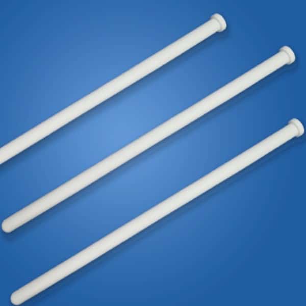
Dedusting:
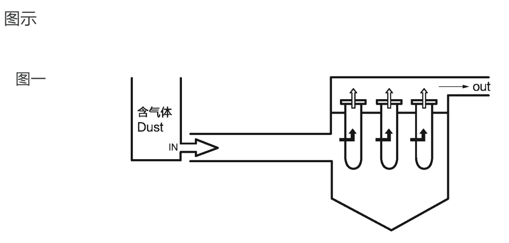
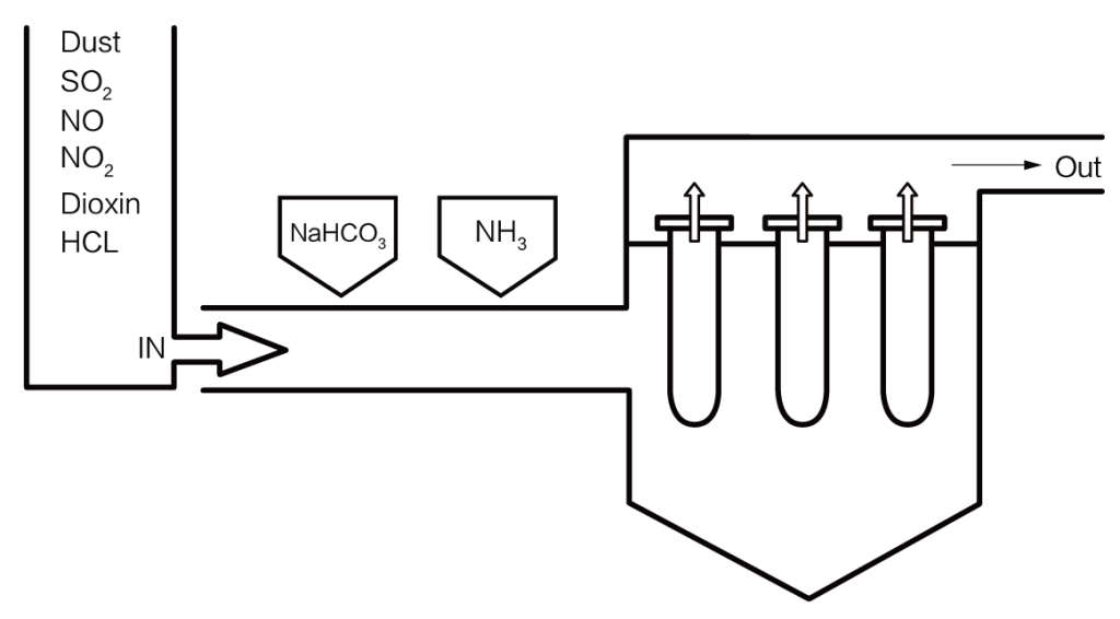
The dedusting filter bin is divided into upper and lower parts. The lower part is the air inlet filter bin, and the upper part is the air outlet clean bin. The upper and lower bins are separated by a perforated fixing plate. The ceramic fiber filters are suspended vertically on the holes of the fixing plate. After the high temperature dusty gas enters into the air inlet filter bin, under the action of the high temperature induced draft fan, it goes through from the outside wall of the ceramic fiber filter into the inside filter, and then it is discharged from the inside filter to the air outlet clean bin(figure 1).
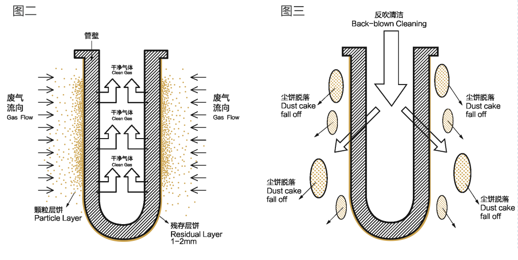
At this time, the dust in the gas will be blocked on the outside wall of the ceramic fiber filter, and the dust cake on the outside wall of the filter will become thicker and thicker. Only the clean gas could go through the wall of the filter into the inside filter (figure 2).
As the dust cake accumulates thicker and thicker on the outside wall of the ceramic fiber filter, the resistance of the filter will become larger and larger, and so does the internal and external pressure difference of the filter. At this time, the system will start backflush cleaning program. The compressed air will be blown back into the ceramic fiber filter. The dust cake on the outside wall of the filter will fall off(figure 3). Then the ceramic fiber filter can start a new round of dust removal procedures.
Please refer to the figure below:
Why Fiber Diameter Control Matters: 3–5 μm is Not Arbitrary
The filtration precision of a ceramic fiber filter is determined primarily by the fiber diameter and the packing density (porosity). Finer fibers create smaller pore spaces between fibers, which capture smaller particles. However, there’s a trade-off: finer fibers are more fragile and harder to produce consistently, and they create higher pressure drop for the same porosity. Our automated fiber spinning line controls diameter to 3–5 μm with <5% standard deviation — this is the optimal range that gives us 1 μm filtration precision at reasonable pressure drop (100 Pa clean, 2,000–2,300 Pa operating) while maintaining mechanical strength (4 MPa tensile, 500 N radial crush) for pulse-jet cleaning.
Some competitors claim 1–2 μm fibers for “higher efficiency,” but in practice these ultra-fine fibers break during handling, shipping, and installation, creating weak points in the filter structure. We’ve tested samples from other suppliers and found fiber diameter variation of ±40% (versus our ±5%), which creates local weak spots that fail prematurely under thermal cycling and mechanical stress. Our 17 years of production experience has taught us that 3–5 μm diameter with tight process control delivers the best combination of filtration performance, mechanical durability, and manufacturing consistency.
Filtr ceramiczny włóknisty katalityczny
Desulfurization and de-acid gas(HCl/HF)
Lime or NaHCO3 can be used to react with acid gas. The reactants (solid compounds) will be left on the outside wall of the filter when it goes through the filter, while the harmless gas will be discharged from the chimney. This process is similar to the dedusting process. The reaction equations are as follows:
NaHCO3+SO2=NaHSO3+CO2 (small amount of SO2)
NaHCO3+HCL= NaCl+CO2+H2O
NaHCO3+HF= NaF+CO2+H2O
Uwaga: In the actual working conditions, it is rare to have desulfurization alone. Usually, desulfurization and denitrification are carried out at the same time. At this case, the catalytic ceramic fiber filters are needed.
Denitrification:
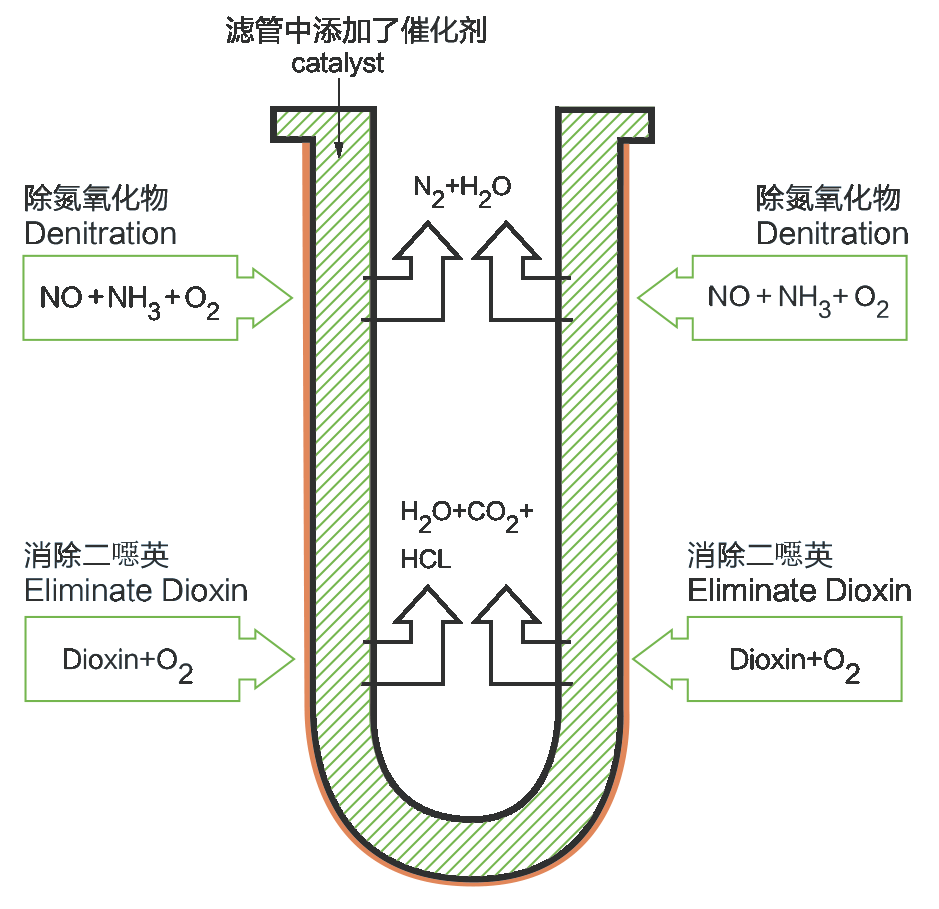
The denitrification reaction could be accelerated by adding a catalyst to the wall of the ceramic fiber filter. With traditional technology, Liquid ammonia or Urea /CO(NH2)2 are added to react with NOx. The reaction formulas are as follows:
4NO+4NH3+O2 = 4N2+6H20
2NO2+4NH3+O2 = 3N2+6H20
4NO+2(NH2)2CO+O2 = 4N2+4H20+2CO2
Usuwanie dioksyn:
Katalizator w filtrze z włókna ceramicznego może nie tylko katalizować usuwanie tlenków azotu (NOx), ale także katalizować usuwanie dioksyn. Pod działaniem katalizatora dioksyny reagują z tlenem, tworząc nietoksyczne substancje, takie jak CO2, H2O i HCl. Równanie reakcji jest następujące:
C12HnCl8-nO2+(9+0.5n)O2→(n-2)H2O+12CO2+(8-n)HCl

ü Skuteczność usuwania pyłu do 99,9%
ü Skuteczność usuwania HCl do 97%
ü Skuteczność usuwania SOx do 95%
ü Skuteczność usuwania NOx do 95%
ü Skuteczność usuwania dioksyn do 97%
Wsparcie techniczne od inżynierów, którzy projektują filtry
Gdy kontaktujesz się z Anchor Technology z pytaniem technicznym dotyczącym zasady filtracji, projektowania systemu lub rozwiązywania problemów, rozmawiasz z tymi samymi inżynierami, którzy projektują i testują nasze filtry w naszym zakładzie w Guangzhou. Nasz zespół techniczny obejmuje naukowców zajmujących się materiałami, którzy optymalizują skład włókna ceramicznego, inżynierów mechaników, którzy projektują strukturę filtra i systemy czyszczenia pulsacyjnego, oraz inżynierów procesowych, którzy określają kompletny system odpylania dla Twojego zastosowania. Nie tylko sprzedajemy filtry — zapewniamy pełne wsparcie techniczne od wstępnej oceny wykonalności poprzez instalację, rozruch i długoterminową optymalizację wydajności.
Jeśli oceniasz filtrację z włókna ceramicznego dla nowego projektu lub rozwiązujesz problemy z istniejącą instalacją, skontaktuj się z naszym zespołem inżynierów pod adresem [email protected] lub WhatsApp +86 137 0305 0828. Przeanalizujemy Twoje warunki procesowe, skład gazu i wymagania dotyczące wydajności oraz przedstawimy uczciwą ocenę techniczną, czy filtry z włókna ceramicznego są właściwym wyborem — w tym przypadki, w których zalecamy inną technologię, ponieważ jest bardziej opłacalna dla Twojego konkretnego zastosowania.
Często zadawane pytania dotyczące zasady działania filtra ceramicznego
→ Zobacz nasze rury filtracyjne niekatalityczne i świece filtracyjne katalityczne do zastosowań przemysłowych.
 English
  Deutsch
  简体中文
简体中文  한국어
한국어  日本語
日本語  Español
  Français
  Italiano
  Türkçe
  Tiếng Việt
  Português
  हिन्दी
  العربية
  Polski
  繁體中文
繁體中文